Legrand RFB2 User Manual
Page 3
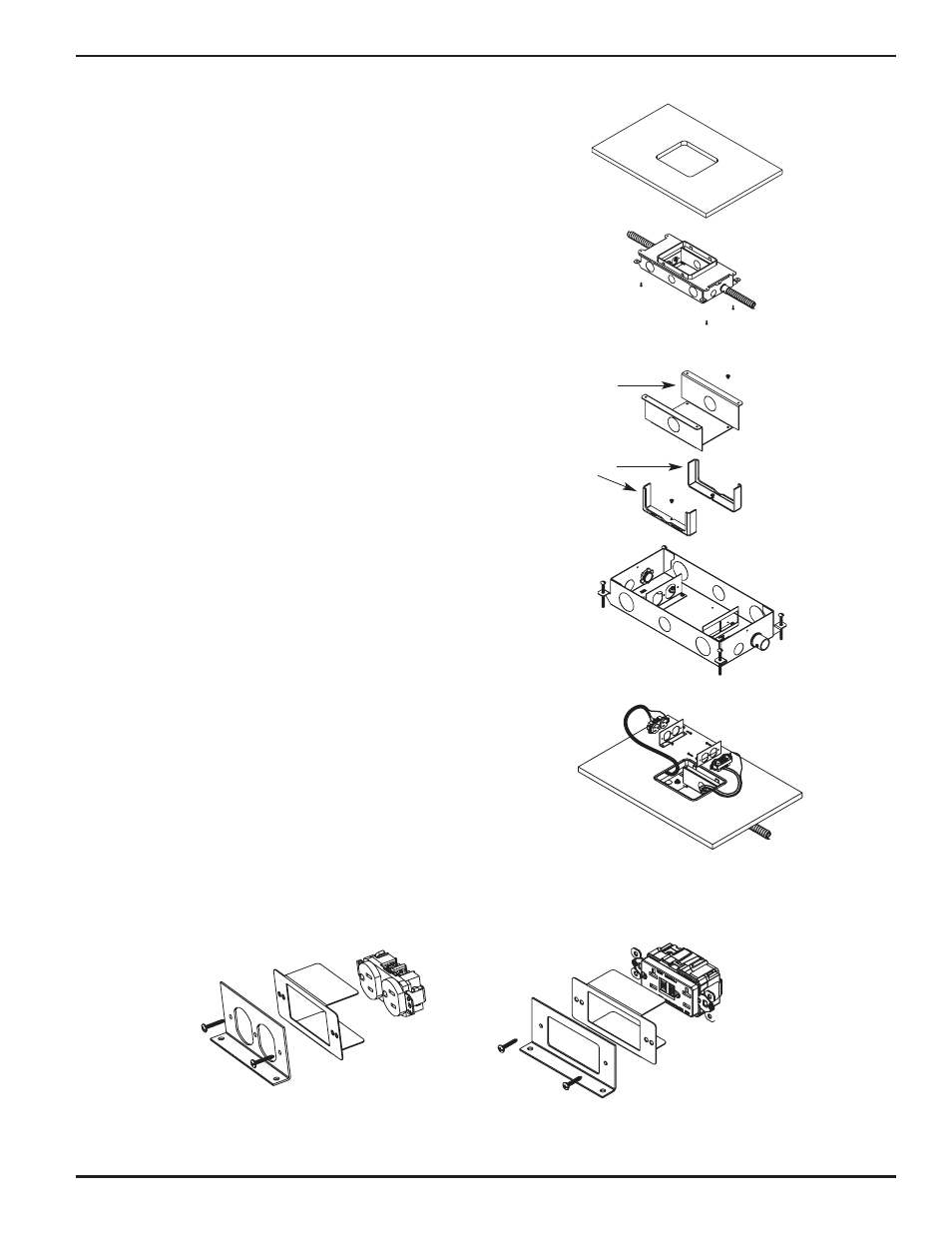
WOOD FLOOR INSTALLATION:
Step 1. Determine box location and orientation.
Step 2. Cut a 6" [152mm] x 7 1/4" [184mm] opening in
wood floor.
Step 3. Remove box cover and desired knockouts. Attach
appropriate connectors per wiring type (mc cable,
conduit, nonmetallic, sheathed, etc., not supplied
by Wiremold) to steel base. Remove tunnel block(s)
as required if power is to be used on both sides of
the box.
Step 4. Re-attach cover to box with two (2) #8-32 x 1/2" long
screws provided.
Step 5. Align plastic trim ring on top of box with opening in
floor, and secure box to underside of floor with four (4)
#8 or four (4) #10 pan head sheet metal screws, (not
supplied by Wiremold), through the four (4) holes
provided in cover.
Step 6. Wire devices, (not supplied by Wiremold), making sure
that any ground leads are properly connected to
ground screws. Attach the receptacle to the
receptacle mounting bracket using the #6-32 screw
provided. Secure the receptacle to the receptacle
mounting bracket with two (2) additional screws and
nuts, (not provided). Attach the receptacle mounting
bracket(s) to the base with the two (2) #8-32 mounting
screws provided.
Step 7. Complete procedure by installing a Wiremold
FloorPort Activation, (sold separately), using the
installation instructions provided with that unit.
NOTE: Box is supplied with tunnel bracket, tunnel blocks
and device mounting brackets installed. If the
same service is to be used in both compartments,
it will be necessary to remove one or both of the
tunnel blocks to allow for pass through of the
service wiring. The tunnel blocks are accessible by
removing the tunnel support. The installer may do
this either pre- or post-installation.
NOTE: Use insulator provided with the following catalog
numbers, installed as shown: RFB2DP, RFB2GFI.
Tunnel Blocks
Tunnel Support