Rfb4 recessed floor box, Rfb4-4db recessed floor box – Legrand RFB4 User Manual
Page 2
A
B
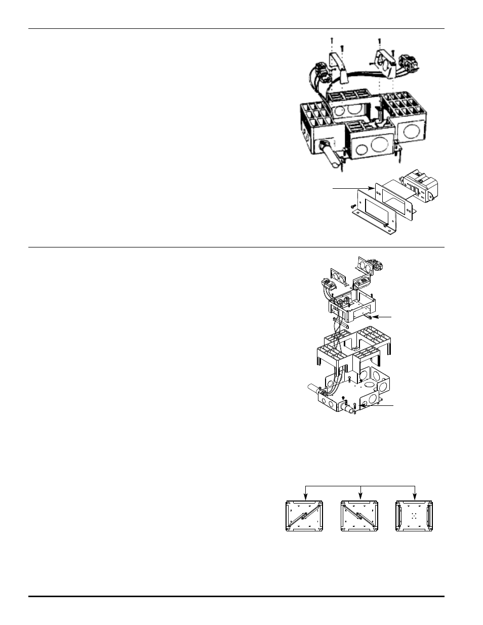
Step 7 Locate box and chip away concrete located in mudcap. Remove mudcap
and device plates. Remove tunnelblocks from the combination bracket fingers.
Clean out any debris. If concrete does not break cleanly around preset, the
activation might not be properly supported. If edges of FloorPort
™
Series Activations
are not supported by concrete on all sides, repair of excessive concrete spalling is
required.
Step 8
Wire devices (not included) in accordance with the National Electrical Code or any
local code that applies. Make sure that any ground leads are connected to ground
screws. Attach the receptacle to the receptacle mounting bracket using #6-32 screw
provided. Attach the receptacles to the receptacle mounting brackets with two
additional screws and nuts (not provided). Attach the receptacle mounting bracket to
the combination bracket using two #10-24 mounting screws provided.
Step 9
Complete procedure by installing a FloorPort Series Activation (sold separately)
using the installation instructions provided with the unit. instructions provided with
the unit.
This box and activation are UL Listed for use with tile, terrazzo, and
carpet floors.
Use insulator provided with the following catalog numbers:
RFB-GFI, CIHT-GFI, RFB-GFI-SS, RFB-GFI-4DB.
RFB4 Recessed Floor Box –
After Concrete Pour:
Tunnel Block
(See Step Four)
Adjusting Screw
Step 1
Remove knockouts and attach conduit to base using proper conduit adapters
(not supplied).
Step 2
Slip housing over base. Using the adjusting screws provided adjust box so that
top is 1/16" [1.6mm] below screed line.
Step 3
Once positioned, connect conduit to adapters and anchor box to the subfloor by
wire or nails through the slot adjacent to the adjusting screws.
Step 4
If all four compartments are not being used for single service, tunnel blocks may
be installed to provide service isolation when feedback through wiring is not
required (see Tunnel Block Arrangements Illustration).
Step 5
Insert combination bracket inside of housing and mount to base with four #10-24
x 5/8" [15.9mm] machine screws.
Step 6
Leave receptacle brackets in shrink wrapping until concrete is set and receptacles
are ready to be installed.
Step 7
Insert unused tunnel blocks inside of box and insert mudcap.
WARNING: Pour concrete to 1/16" [1.6mm] above box housing. Pours of
1/4" [6.4mm] or more over box housing will make it difficult to
breakout the mudcap and cause excessive spalling.
WARNING: Compartments for power applications must be configured to
allow either direct access or via tunneling to one of the two
grounding screws in either compartment.
RFB4-4DB Recessed Floor Box –
Before Concrete Pour:
Step 1
Locate box and chip away concrete located in mudcap. Remove
mudcap and unused tunnel blocks. Clean out any debris.
tep 2
Attach receptacles (not supplied) to the receptacle brackets, using
#6-32 screw provided. Attach the receptacles to the receptacle
mounting brackets with two additional screws and nuts (not
provided). Wire devices (not included) in accordance with the
National Electrical Code or any local code that applies. Make sure
that any ground leads are connected to ground screws before
securing receptacle brackets using #6-32 x 3/8" [9.5mm] R.H.M.S.
Step 3
Complete procedure by installing a FloorPort Series Activation
using the instructions provided with the unit.
Possible Tunnel Block Arrangements
WARNING:
If concrete does not break cleanly around preset,
the activation might not be properly supported. If
edges of FloorPort Activations are not supported
by concrete on all sides, repair of excessive
concrete spalling is required.
RFB4-4DB Recessed Floor Box –
After Concrete Pour:
Insulator