Legrand WMFB User Manual
Page 2
KEYSTONE JACKS
A. See the instructions enclosed with the product for specific wiring.
B. Mount the device in box by sandwiching the device to the box with the
intermediate sub-plate using provided #6-32 x 3/4" pan head
mounting screws. Note: Orient the Sub-plate to say “THIS SIDE UP”.
For the two port, attach the device to the box by screwing the strap directly
to the box using provided #6-32 x 3/4" pan head mounting screws.
C. Place gasket over the box flange.
D. Assemble o-rings to the provided #6-32 x 1" oval head screws and
use these to assemble the cover plate to the box. Torque to 10 in/lbs
ensuring the gasket stays in place under the cover plate.
COMBO RECEPTACLE/KEYSTONE
This device should be installed in accordance with all appropriate codes
and standards. Warning: Turn off power to outlet box, using breaker or
fuse at service entrance. Verify that power has been removed by testing
with a circuit tester at the outlet box. Caution: This device is for use with
copper or copper-clad wire only.
A. After removing power as described above, use strip gauge on back of
outlet to strip all wires to desired length.
B. Attach wires according to the diagram below. The terminal screws
accept up to #12 AWG wire. Loop wires around screws in a
counterclockwise fashion. Fasten terminal screws securely. Loosely
fastened wires may result in outlet failure and/or fire hazard.
C. Ensure divider is in place in box to separate high voltage from low
voltage. WARNING: FAILURE TO INSTALL DIVIDER CAN CAUSE
FIRE, SERIOUS INJURY OR DEATH.
D. Assemble the desired Keystone Jack to the strap and wire per the
instructions enclosed with the product.
E. Attach the device to the box by screwing the strap directly to the box
using provided #6-32 x 3/4" pan head mounting screws. Note: Orient
the Sub-plate to say “THIS SIDE UP”.
F. Place gasket over the box flange.
G. Assemble o-rings to the provided #6-32 x 1" oval head screws and
use these to assemble the cover plate to the box. Torque to 10 in/lbs
ensuring the gasket stays in place under the cover plate.
D
D
C
B
D
D
C
B
B
B
G
G
F
E
E
C
E
E
G
G
F
C
D
D
C
B
B
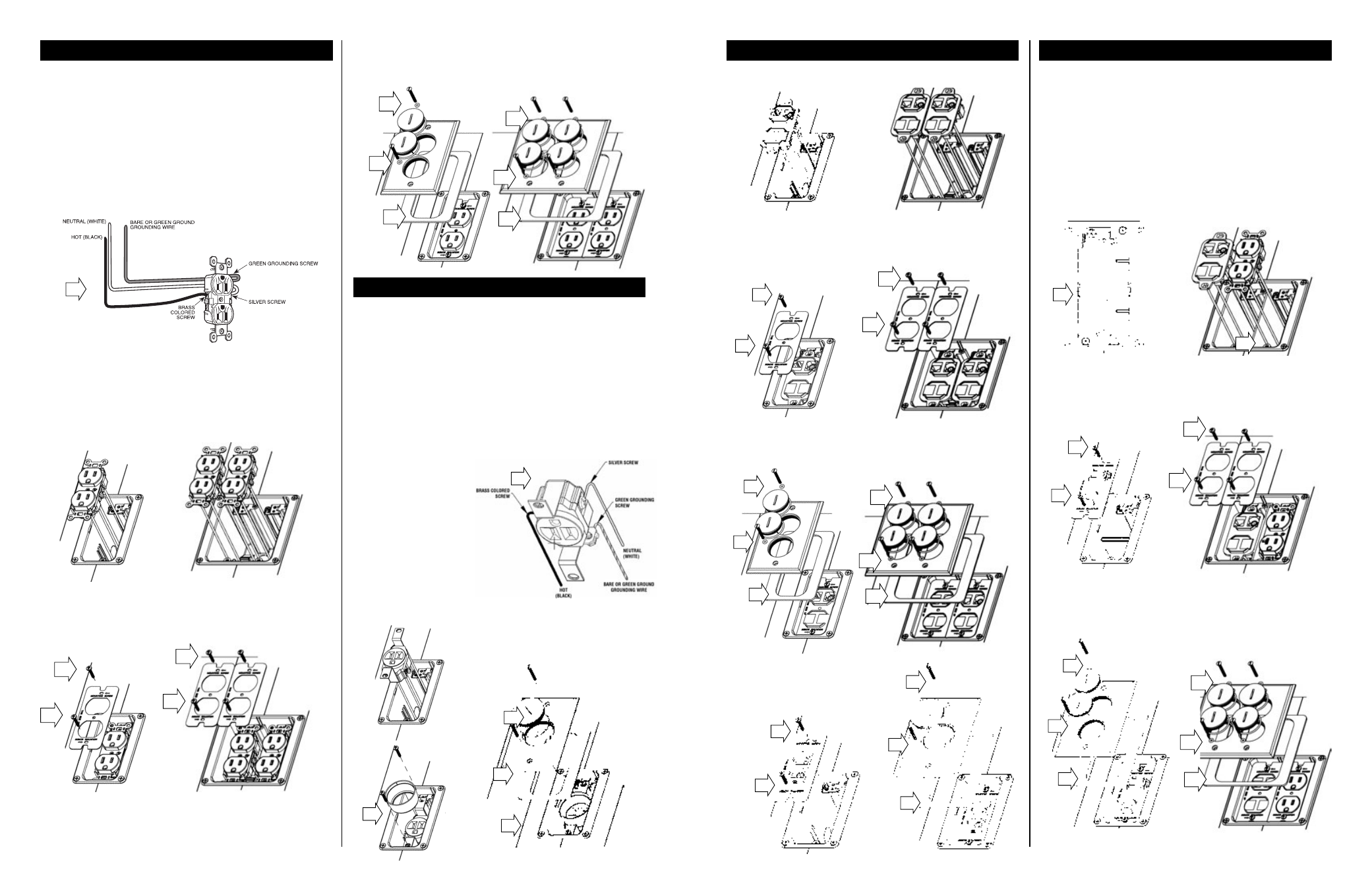
INSTALLATION INSTRUCTIONS
This device should be installed in accordance with all appropriate codes
and standards. Warning: Turn off power to outlet box, using breaker or
fuse at service entrance. Verify that power has been removed by testing
with a circuit tester at the outlet box. Caution: This device is for use with
copper or copper-clad wire only.
A. After removing power as described above, use strip gauge on back of
outlet to strip all wires to desired length.
B. Attach wires according to the following diagram. Be sure the wires are
fastened securely either by the terminal screws or through the
speed-wire holes in the back of the outlet. Loosely fastened wires may
result in outlet failure and/or fire hazard. Attach wires using terminal
screws or speed-wire holes: Not both!
C. If using terminal screws: Terminal screws accept up to #12 AWG
wire. Loop wires around screws in a counterclockwise fashion. Fasten
terminal screws securely.
D. If using speed-wire holes: Fully insert #14 AWG solid copper wire
only into the speed-wire holes. Do not use speed-wire holes for
circuits greater than 15 amps. If outlet must be removed, insert
screwdriver blade in the release slot and push it toward the front of the
outlet, releasing the wire. Discard the outlet.
E. Use feed through wires only when wiring to another outlet downstream.
F. Mount the outlet to the box by sandwiching the device to the box with the
intermediate sub-plate using provided #6-32 x 3/4" pan head mounting
screws. Note: Orient the Sub-plate to say “THIS SIDE UP”.
G. Place gasket over the box flange.
H. Assemble o-rings to the provided #6-32 x 1" oval head screws and
use these to assemble the cover plate to the box. Torque to
approximately 10 in/lbs ensuring the gasket stays in place under the
cover plate.
This device should be installed in accordance with all appropriate codes
and standards. Warning: Turn off power to outlet box, using breaker or
fuse at service entrance. Verify that power has been removed by testing
with a circuit tester at the outlet box. Caution: This device is for use with
copper or copper-clad wire only.
A. After removing power as described above, use strip gauge on back of
outlet to strip all wires to desired length.
B. Attach wires according to the diagram below. Be sure the wires are
fastened securely by the terminal screws.
Loosely fastened wires may result in outlet failure and/or fire hazard.
Terminal screws accept up to #12 AWG wire. Loop wires around
screws in a counterclockwise fashion. Fasten terminal screws securely.
C. Mount the outlet in box by
screwing the strap directly
to the box using provided
#6-32 x 3/4" pan head
mounting screws.
D. Place the shell over the
single receptacle.
E. Place gasket over the box
flange.
F. Assemble o-rings to the
provided #6-32 x 1" oval
head screws and use these
to assemble the cover
plate to the box. Torque to
10
in/lbs
ensuring
the
gasket stays in place under
the cover plate.
DUPLEX RECEPTACLE(S)
B
F
F
F
F
H
H
G
H
G
H
B
C
F
F
E
DATACOM KEYSTONE TWO & FOUR PORT
SINGLE RECEPTACLE