V2417 internal elbow wire capacity, 2400wc wire clip – Legrand V2400 User Manual
Page 2
The Wiremold Company
U.S. and International:
60 Woodlawn Street • West Hartford, CT 06110
1-800-621-0049 • FAX 860-232-2062 • Outside U.S.: 860-233-6251
Canada:
850 Gartshore Street • Fergus, Ontario N1M 2W8
1-800-741-7957 • FAX 519-843-5980
40063R2 – Updated July 2004 – For latest specs visit www.wiremold.com
© Copyright 2004 The Wiremold Company All Rights Reserved
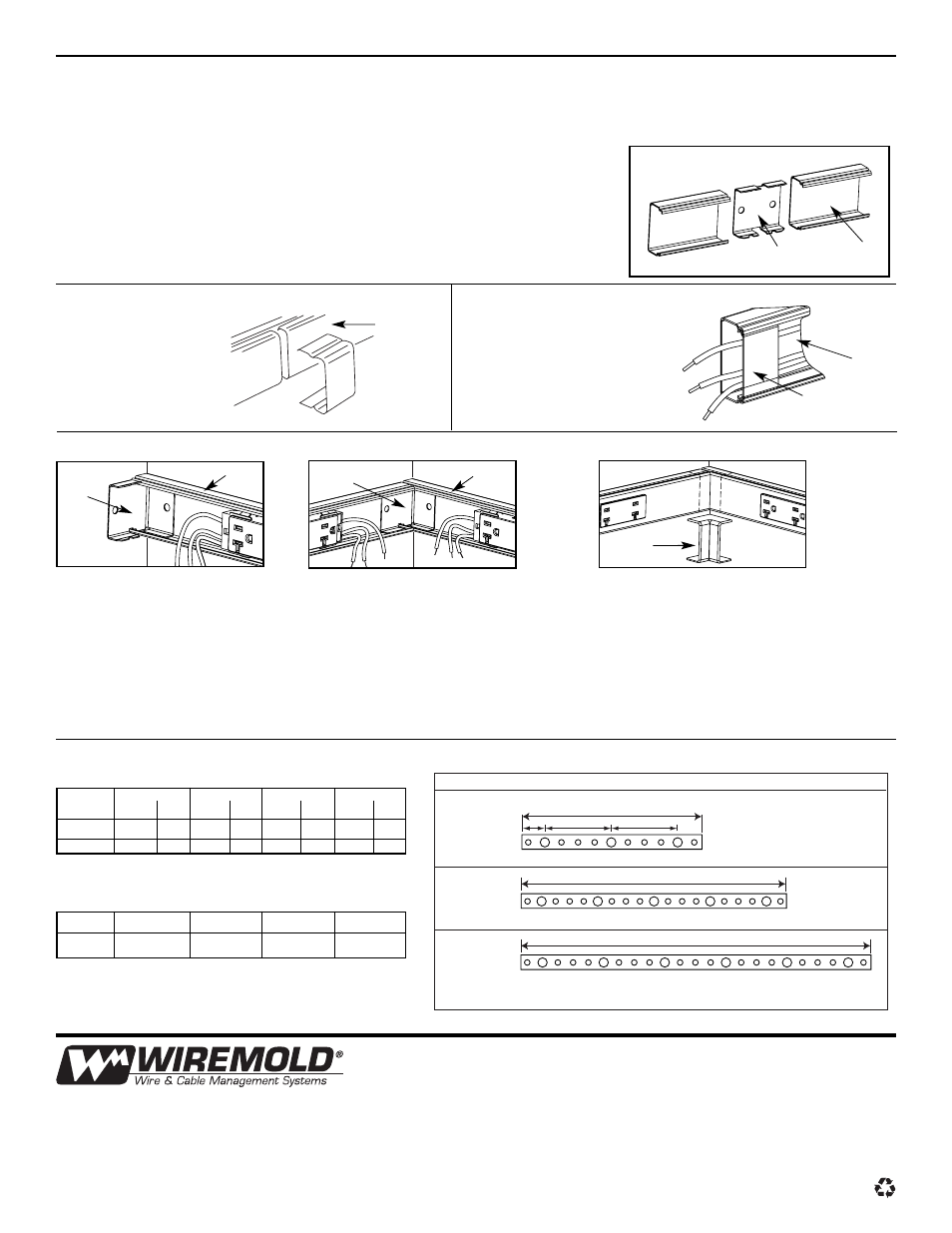
COUPLING TWO PLUGMOLD V2400 WIRED SECTIONS TOGETHER TO EXTEND RUN (USING 2401 COUPLING)
V2406 CONNECTION COVER
Insert 2401 Coupling halfway into one end
of raceway base. Mount raceway using No.
10 Panhead screws.
Insert second raceway base section onto
the opposite end of of 2401 Coupling.
Mount second raceway section with No.
Panhead screws.
Connect green conductor in feed which
is connected directly to the service
grounding terminal using 2409 Ground
Clamp or equivalent approved method
for equipment grounding connections.
Connect black and white harness wires to
black and white feed wires with W30 Wire
Connectors (available separately) inserting
only conductors of same color in a
connector. See “W30 Wire Connectors…
How to Use” Do not use W30 Wire
Connectors with Ground wires. Any
unused wire leads must be individually
closed up with a wire nut. Do Not connect
unused leads together.
Snap V2410A Fitting Cover onto raceway
base. Cut Raceway cover to fit and snap
onto raceway base.
2401 Coupling
V2400B
V2400C
V2406
Connection
Cover
V2417
Coupling
Base
V2400B
V2400B
2400WC
Wire Clip
V2406 may be used to
cover gaps between
raceway covers. Snap
V2406 onto raceway
at each joint.
V2417 INTERNAL ELBOW
WIRE CAPACITY
Insert short end of V2417
Coupling Base into V2400B
Raceway Base. Mount the
assembly to surface.
2400WC WIRE CLIP
Use 2400WC Wire Clips
(available separately) if
necessary to contain wires.
V2417
V2400B
Insert the other V2400B Base into V2417
Coupling. This base section must be in
contact with base already assembled to
short leg of V2417 Coupling Base. DO
NOT LEAVE ANY GAPS BETWEEN THE
TWO BASES. Mount to surface with No.
10 Panhead screws.
V2417
Cover
Install raceway cover next. If necessary
use a blank cover piece for covering any
exposed area. DO NOT LEAVE ANY
GAPS BETWEEN RACEWAY COVERS.
Snap V2417 Cover onto raceway cover
at corner.
NOTE: FOR EASE OF INSTALLATION AT CORNERS – Cut out any receptacle within 4" of wall corner. This will allow sufficient space
within raceway for wire connections where two runs meet. Cut a blank raceway cover piece to fit over any exposed area, if necessary.
#8 #10 #12 #14
THHN TW
THHN TW
THHN TW
THHN TW
15 AMP
13
10
26
22
41
28
56
36
20 AMP
13
10
26
22
41
28
–
–
RACEWAY (without receptacles)
#8 THHN
#10 THHN
#12 THHN
#14 THHN
20 AMP
2
4
6
–
PLUGMOLD MULTIOUTLET SYSTEM
(20 Amp Prewired GB Series)
Wired Section Nos.
Base
V24GB306
V24GB506
V24GB512
V24GB606
V24GB612
V24GB618
36"
6"
12"
12"
3" 6" 9" 12" 15"
21" 24" 27"
33"
60"
3" 6" 9" 12" 15"
21" 24" 27"
33" 36" 39"
45" 48" 51"
57"
72"
3" 6" 9" 12" 15"
21" 24" 27"
33" 36" 39"
45" 48" 51"
57" 60" 63"
69 "