Legrand ECB User Manual
Page 11
11
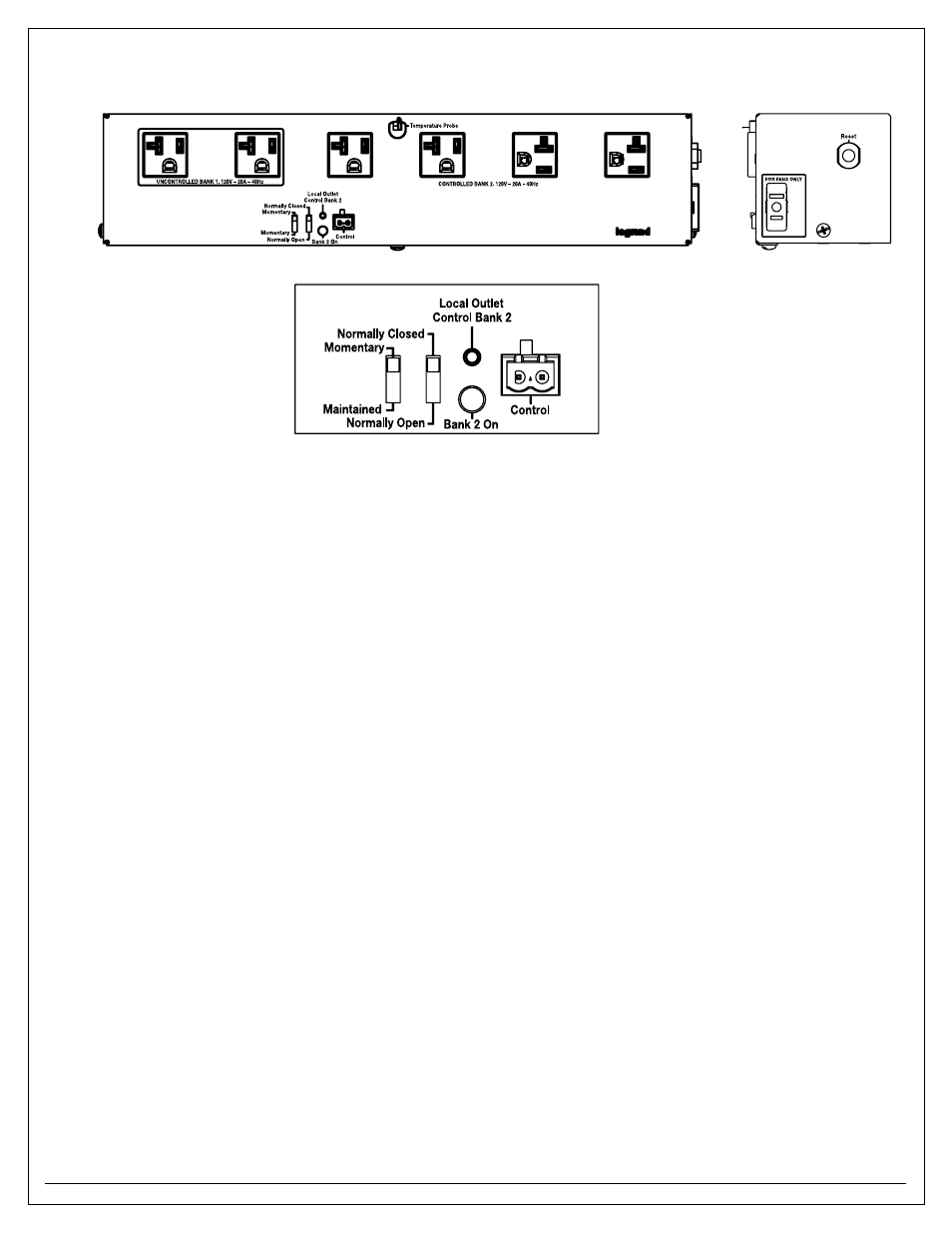
Controlled Receptacle module Setup Guide for ECB2S-CR & ECB2SP-CR
Control - terminal Block:
The unit is controlled by a customer provided dry contact, (
imPoRtANt> Do not connect external control voltage). This is a 2-wire, class
2 circuit, is to be connected to the pluggable terminal block. The current on the control conductors is 1 ma @ 5VDC.
The customer provided contact closure connected to remote control terminal block, may be either momentary or maintained; additionally
the contact closure may be normally open or closed, (see below).
Normally open/Normally Closed (No/NC) switch:
The unit may be controlled be a Normally Open or a Normally Closed contact arrangement.
This switch works in conjunction with the MOM/MAINT switch (described below).
momentary/maintained (mom/maINt) switch:
momentary operation:
A contact closure is required for the control PCB to process the control signal. Each subsequent closure will alternately turn off and on
the power to the controlled receptacle.
maintained operation:
With the NORMALLY OPEN/CLOSED switch in the NORMALLY OPEN position, a maintained contact closure will energize the controlled
receptacle via the control circuit. When this maintained contact is removed, the receptacle will become de-energized.
With the NORMALLY OPEN/CLOSED switch in the NORMALLY CLOSED position, a maintained contact closure will de-energize the
controlled receptacle via the control circuit. When this maintained contact is removed, the receptacles will become energized.
local outlet Control Bank 2 - test switch:
This switch is connected in parallel to the control terminal block, and allows local control of the unit for diagnostic purposes.
Bank 2 on - status indication lEd:
This green LED indicator will be illuminated when the controlled receptacle is energized.
reset:
20 A resettable supplementary circuit protection. Located on the right side of the power module