Legrand FD User Manual
Page 3
3
3. Installing the Duct
a. After the junction boxes are roughed in, position duct supports or couplings and lay the duct in place (See Steps 5 & 6).
b. Begin at one corner of the layout, insert duct in a box opening and work toward the next box. Join each length to the
next with a duct coupling, butting the ends tightly and tighten the grounding screws. Cut last length of duct as required
to fit snugly into the next box opening.
c. Whenever possible, begin each run of duct with a full piece. However, if a field cut section of duct is needed, be sure
that the distance from the field cut end to the center of the first opening is the proper length to maintain the uniform
spacing between openings. Cutting of duct is to be performed in the field as required. All sharp edges must be removed
on all field cut sections of duct.
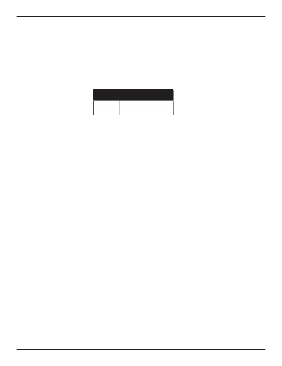
d. The distance between duct ends varies within each junction box for different systems. The table on the next page shows
the correct distance for each junction box:
12FB
222FB
3222FB
8 5/16"
11 1/4"
14 3/4"
[211mm]
[286mm]
[375mm]
Junction Box
Distance Between Duct
Cat. No.
Ends Within Junction Box
e. In all cases where the duct is to be fitted into a casting, be sure the duct is fully extended into the fitting.
3. Leveling Junction Boxes
a. Junction boxes feature four exterior leveling feet for leveling and height adjustment prior to the concrete pour. After all
junction boxes are in place, use these leveling feet to level the tops to the finished concrete screed level. Standard foot
provides approximately 1 1/2" [38mm] upward adjustment.
b. After all junction boxes have been leveled, care should be taken to insure that they will not be moved during the concrete
pour. This is accomplished by driving studs or nails through the holes in the leveling feet. Grouting the box firmly in place
before final pour will prevent movement during the pour.
c. A solid foundation of grout or concrete must be provided beneath the entire junction box to prevent excessive
cover plate deflection and damage.
5. Installing Duct Supports or Couplings
Couplings:
Couplings/Supports or combination couplings/adjustable supports are used to hold flushduct securely in place before the
concrete is poured.
“Couplings” have no vertical adjustment. “Couplings/Supports” have 1" [25mm] vertical adjustment. “Combination
Couplings” have various adjustment ranges – up to 5" [127mm] from the bottom of the duct to the top of the slab or
form. Install duct supports 5'-0" [1524mm] from each junction box and on 5'-0" [1524mm] maximum centers throughout
the system. Sufficient space must be provided below the duct to allow for the flow of grout or concrete that will support
the duct system. All supports should be firmly attached to the form or slab.
6. Final Adjustments to the System Prior to the Concrete Pour
a. After all the boxes, duct runs, and roughing-in material are in place, the following should be checked before concrete
is poured:
1. All openings in the junction boxes are fitted with duct, conduit adapters or box closures.
2. The ends of all duct runs are capped.
3. All openings have screw plugs.
4. All openings have plugs.
b. Just prior to concrete pour or grouting, be certain that all ducts are tightly joined and grounding screws are securely
tightened. All openings must be sealed with sealing compound or duct tape and the entire system must be flush with the
existing floor or leveled to the screed surface. Advise the general contractor that concrete or grout must be placed flush
with the top surface of the duct and boxes.