Options for 90° internal corners – Legrand AL5200 Series Aluminum Raceway User Manual
Page 2
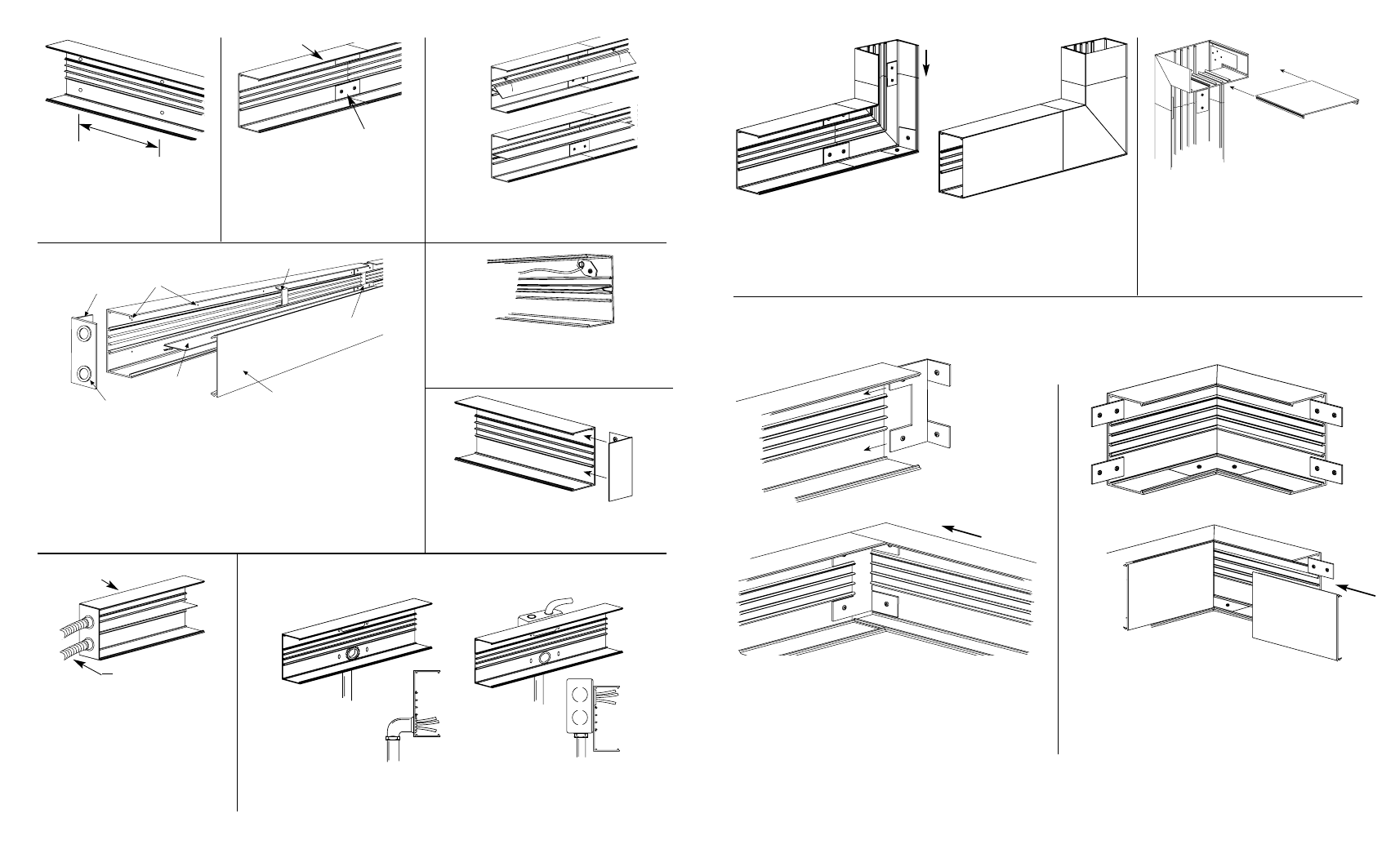
AL5214 Wall Box Connector connects to two in line AL5200B base sections via
AL5201 Couplings supplied.
AL5200 Base
Direct Feed
Feeding From Wall Box
Using AL5214 Wall Box Connector
(AL5210B2 shown)
1/2" or 3/4" Conduit
End-feeding: AL5210B2/ AL5210B1/
AL5210B3 Series End Fittings have
concentric 1/2" and 3/4" trade size
KOs in end. Provide electrical feed
through KOs. Insert fitting into end of
raceway base. Secure in place by
tightening two screws.
3
6
5
1
2
4
Snap-in
divider
(optional)
1 - Provide electrical feed through
1/2" or 3/4" KOs in AL5210B2
End Cap.
2 - Attach base section to mounting
surface by drilling 9/32" holes in
the base then fastening with #8 flat
head screws.
3 - Secure conductors in place with
AL5200WC Wire Clip.
4 - Join additional raceway sections
with two AL5201 Couplings.
5 - Close ends with AL5210B2
End Caps.
6 - Snap cover into base to
complete installation.
To attach AL5200B Series Base
sections to mounting surface; drill
9/32" holes in the base (approx.
18" O.C.). Fasten Base with #8 flat
head screws.
18"
At end of AL5200 Raceway run: slide AL5210B
Blank End Fitting in last base section. Secure in
place by tightening two screws.
AL5201
Base Sections
At AL5200B Base section butt joints:
slide two (2) AL5201 Couplings into
first base section. Mount next base
to surface. Center couplings on joint.
Tighten locking screws.
Snap in AL5200D Divider into raceway base
as shown. Refer to cross-sectional drawings
above for versatile divider locations.
Position AL5209 Ground Clamp into ribs in
AL5200B Base. Fasten mounting screw.
Attach ground wire to green ground lug.
At 90° turn on same surface, position AL5211 Flat Elbow at end of AL5200B
Base. Position next base section onto other end of AL5211. Center couplings
over base joints and tighten screws. Install AL5211 Covers and AL5200C
Covers as shown after wiring.
For connecting a vertical run of AL5200
with a horizontal overhead run with its
cover facing up. Assemble AL5217N to
raceway bases with AL5201 Couplings
supplied.
Install one side of AL5217A Internal Coupling, BEFORE
mounting raceway base. Fasten first base section to
wall, then slide adjoining base onto coupling legs.
Tighten all four coupling screws.
Install AL5217 to first raceway base, BEFORE mounting
raceway base. Fasten base section to surface. Butt next
section of base. Center couplings over base joints,
tighten set screws.
AL5211
AL5211 With Cover
AL5217A Internal Corner Coupling
AL5217 Internal Elbow
Options for 90° Internal Corners:
System Layout
AL5217N