Legrand SPMJ SpecMate Wireway Systems User Manual
Page 2
Smaller Inside Dimensions of Wireway
Maximum Conductor Size AWG or MCM
Inches
[mm]
Conductor
[mm
2
]
1 1/4
31.8
6
13.3
2
50.8
3
26.7
2 1/2
63.5
2
33.6
3
76.2
1
42.4
3 1/2
88.9
2/0
67.4
4
102.0
4/0
107.2
4 1/2
114.0
250
127.0
5
127.0
350
177.0
6
152.0
500
253.0
8
203.0
900
456.0
10
254.0
1250
633.0
12
305.0
2000
1013.0
The Wiremold Company
U.S. and International:
60 Woodlawn Street • West Hartford, CT 06110
1-800-621-0049 • FAX 860-232-2062 • Outside U.S. 860-233-6251
In Canada:
850 Gartshore Street • Fergus, Ontario N1M 2W8
1-800-741-7957 • FAX 519-843-5980
INS00007R1 – Updated June 2001 – For latest specs visit www.wiremold.com
© Copyright 2001 The Wiremold Company All Rights Reserved
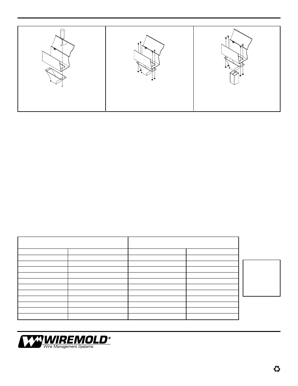
Installation of Tele-Power Pole Adapter:
1. Locate the Pole Adapter on the Wireway.
Drill holes in the appropriate locations to
match the holes in the Pole Adapter.
Cut and grommet hole to match Pole
Adapter Entrance Feed.
2. Bolt the Pole Adapter to the underside
of the Wireway. No sharp edges
should remain in the Wireway. (Bolts
not furnished.)
3. Insert the Wiremold NP600 Series Tele-
Power Pole into the underside of the
Pole Adapter. Tighten the two set
screws (furnished) onto the pole.
National Electrical Code (NEC):
Article 362-5 of the NEC (1999) states that “The sum of cross-sectional areas of all contained conductors at any cross section of
the wireway shall not exceed 20 percent of the interior cross-sectional area of the wireway” and that “Wireways shall not contain
more than thirty current carrying conductors at any cross section.” An important exception to this is that “where the derating factors
specified in Article 310 – 15(b)(2)(a), are applied, the number of current-carrying conductors shall not be limited, but the sum of the
cross-sectional areas of all contained conductors at any cross section of the wireway shall not exceed 20 percent of the interior
cross-sectional area of the wireway.”
Where the conductors enter the wireway through the bottom or the sides, the maximum conductor size is limited due to the need
to control the bend radius of the conductor. See the chart entitled “Conductor Size Based on Bending Space,” for the maximum
conductor size applicable for this situation.
Please see Article 362 of the NEC for more details if required.
Canadian Electrical Code (CEC):
The rules in CEC 12-2104 regarding conductors in wireways are as follows:
(1) Conductors used in wireways shall be the insulated types indicated in Table 19 (CEC) as being suitable for use in raceways.
(2) Except as permitted in Subrule (4) wireways shall contain not more than 200 conductors and the aggregate cross-sectional
area of the conductors and their insulation shall not exceed 20% of the interior cross-sectional area of the wireway.
(3) No conductor larger than 500 kcmil (MCM) copper of 750 kcmil (MCM) aluminum shall be installed in any wireway.
(4) Wireways containing only signal and control conductors may contain any number of conductors but the aggregate cross-
sectional area of the conductors and their insulation shall not exceed 40% of the interior cross-sectional area of the wireway.
(5) The cross-sectional area for conductors in Subrules (2) and (4) shall be determined in accordance with Rule 12-1014(4).
Please see Section 12-2100 of the CEC for more details if required.
Conductor size is based upon the bending space.
For wirefill
charts and
other technical
information, see
The Wiremold
Company’s
Buyers Guide.
Exception: Conductors that enter only at the ends of the run are limited in size only by the 20% fill requirements of the National and
Canadian Electrical Codes.