Legrand TITAN Series v.2 User Manual
Page 2
SINGLE GANG INSTALLATION INSTRUCTIONS
1. Disconnect power to circuit by removing fuse or turn
circuit breakers OFF before installing.
2. For existing installations: Remove wall plate and
switch mounting screws, pull existing switch from wall
box. For new installations: Install a 1-gang wall-box.
3. Disconnect existing switch from circuit. 3-way
installation: Identify the “COMMON” wire (wire
connected to the terminal marked common or odd
colored terminal). For “new” installation identify wire
connected to power source or to the load.
4. Connect dimmer as shown in the wire diagram with
appropriate sized wire connectors (see Table 4).
5. Install dimmer in wall box, with the word “TOP” up, using mounting screws provided.
6. Insert the label, attach the wall plate and restore power to the circuit.
7. Dimmer Set-up Adjustments:
a. Incandescent Dimmer: The Full ON voltage can be reduced to save energy
by reducing the Full ON light level. To change the Full ON light level, slide
the dimmer knob up to its full brightness. DISCONNECT POWER FROM
CIRCUIT, and remove the wall plate. Use a small insulated, screwdriver to
adjust the trim potentiometer. Turn down to decrease the Full ON light level.
b. Magnetic Low Voltage Dimmer: The minimum light level may need
adjustment for variations in low voltage transformers. To change the
minimum light level, slide the dimmer knob down to the lowest
brightness. DISCONNECT POWER FROM CIRCUIT, and remove the wall
plate. Use a small insulated, screwdriver to adjust the trim potentio-
meter. Turn down to decrease the minimum light level.
c. Fan Speed Controls: The minimum fan speed level may need adjustment
for variations in fans. To change the minimum fan speed, slide the knob
down to the lowest level. DISCONNECT POWER FROM CIRCUIT, and
remove the wall plate. Use a small insulated, screwdriver to adjust the
trim potentiometer. Turn down to decrease the fan speed. Make certain
that the fan does not “stall” in any of the ON positions as overheating of
the fan may occur. DO NOT USE THE FAN PULL CHAIN TO CHANGE
SPEEDS AFTER THIS CONTROL IS INSTALLED. THE FAN PULL CHAIN
NEEDS TO REMAIN AT THE MAXIMUM SPEED.
d. Dehummer Fan Speed Controls: No adjustments required. Make certain
that the fan does not “stall” in any of the ON positions as overheating of
the fan may occur. DO NOT USE THE FAN PULL CHAIN TO CHANGE
SPEEDS AFTER THIS CONTROL IS INSTALLED. THE FAN PULL CHAIN
NEEDS TO REMAIN AT THE MAXIMUM SPEED.
e. Fluorescent Dimmers “CDFB”
Series: The minimum light level
may need adjustment for variations
in ballasts. To change the minimum
light level, slide the dimmer knob
down to the lowest brightness.
DISCONNECT POWER FROM CIR-
CUIT, and remove the wall plate.
Use a small insulated, screwdriver
to adjust the trim potentiometer.
Turn up to increase the minimum
light level.
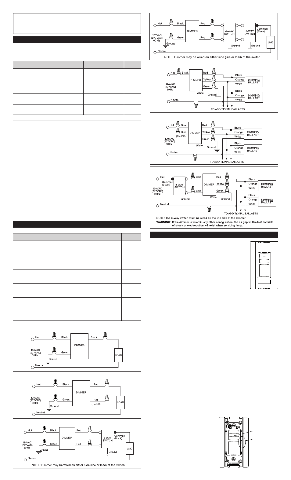
WIRING DIAGRAMS
Table 4
WIRING INFORMATION
IMPORTANT NOTES Read the following before installation:
• Requirements for wire strip length and wire connections.
Table 3 - WIRE NUT USAGE CHART
• Use a separate neutral wire for each phase of a multiphase system
containing a dimmer, and for high power single phase applications where
flickering is present.
• All dimmers can be damaged by improper wiring. Check for short circuits
prior to installing the dimmer.
Procedure for short circuit check:
a. Disconnect power to the circuit by removing fuse or turning circuit
breakers OFF.
b. Install a switch instead of the dimmer. Turn the switch to the “on” position.
c. Turn power ON. If the circuit breaker trips, a short is present. If the light
fails to turn ON and OFF with the switch, the wiring may be incorrect.
d. Correct wiring, if necessary and retest.
e. Install the dimmer only after the light operates properly with the switch.
• Protect from dirt and dust. The dimmer can be damaged from contamin-
ates encountered during the construction process. If lighting is required
prior to the construction process completion, then a switch should be
temporarily installed in place of the dimmer. The dimmer should not be
installed until the construction process is complete.
• Any dimmer damaged by improper installation is not covered under warranty.
• It is normal for the dimmer to feel warm during operation.
• Cleaning Instructions: Wipe dimmer with a damp, clean cloth.
DO NOT clean the dimmer with chemicals or cleaning solutions.
Dimmer Catalog #
Diagram #
CD700, CD1100, CDLV700, CDLV1100, CD1600, CDLV1600,
CD2000, CDFB5, CDFB8, CDFB10, CDFB16, CDFB7-277,
1
CDFB10-277, CDDH16, CDSC6, CDSC12
For Single Pole Installation of: CD703P, CD1103P, CDLV703P,
CDLV1103P, CD1603P, CDLV1603P, CD2003P, CDFB53P, CDFB83P,
2
CDFB103P, CDFB163P, CDFB73P-277, CDFB103P-277
For 3-Way Installation of: CD703P, CD1103P, CDLV703P,
CDLV1103P, CD1603P, CDLV1603P, CD2003P, CDFB53P,
3
CDFB83P, CDFB103P, CDFB163P, CDFB73P-277, CDFB103P-277
For 4-Way Installation of: CD703P, CD1103P, CDLV703P,
CDLV1103P, CD1603P, CDLV1603P, CD2003P, CDFB53P, CDFB83P,
4
CDFB103P, CDFB163P, CDFB73P-277, CDFB103P-277
CD3FB16, CD3FB10-277
5
For Single Pole Installation of: CD3FB163P, CD3FB103P-277
6
For 3-Way Installation of: CD3FB163P, CD3FB103P-277
7
Wire Combinations
Strip Lengths
Color
1#14 & 1#16; 1#14 & 2#18; 2,3#16;
1/2" Except 9/16"
Orange
1#16 & 1-3#18; 3-5#18; 2#18
For #16 & #18 AWG
1#10 & 1#14; 1#12 & 1#14 2, 3#14;
1/2" Except 5/8"
Yellow
2#14 & 1,2#16; 2#14 & 2,3#18;
For #16 AWG
1#14 & 1-4#16; 1#14 & 1-4#18
1#10 & 1,2#12; 1#10 & 1-3#14; 2,3#12;
7/16" Except 1/2"
Red
1#12 & 1-3#14; 1#12 & 3#16; 3,4#14
For #16
1#14 & 1,2#16; 1#14 & 1,2#16;
7/16" For #14 & #16
Ivory
2,3#16; 2-5#18
1/2" For #18
Use Only Copper Wire With This Device.
DIAGRAM 1 (Single-Pole Wiring)
DIAGRAM 2 (Single-Pole Wiring Using 3-Way Preset Dimmer)
DIAGRAM 3 (3-Way Wiring)
DIAGRAM 4 (4-Way Wiring)
DIAGRAM 5 (Single-Pole Wiring)
DIAGRAM 6 (Single-Pole Wiring Using 3-Way Preset Dimmer)
DIAGRAM 7 (3-Way Wiring)
CAUTION: To be installed by a certified electrician or other qualified person.
WARNING: To prevent severe shock or electrocution, always turn power
OFF at the service panel before installing this dimmer, working on the
circuit, or changing a lamp.
Knob
Trim
Potentiometer
NOTE: Never
adjust trim
potentiometer
when circuit
is live.