Wiring diagrams, Wiring information, Single gang installation instructions – Legrand TITAN Series v.4 User Manual
Page 2: Multiple ganging of dimmers
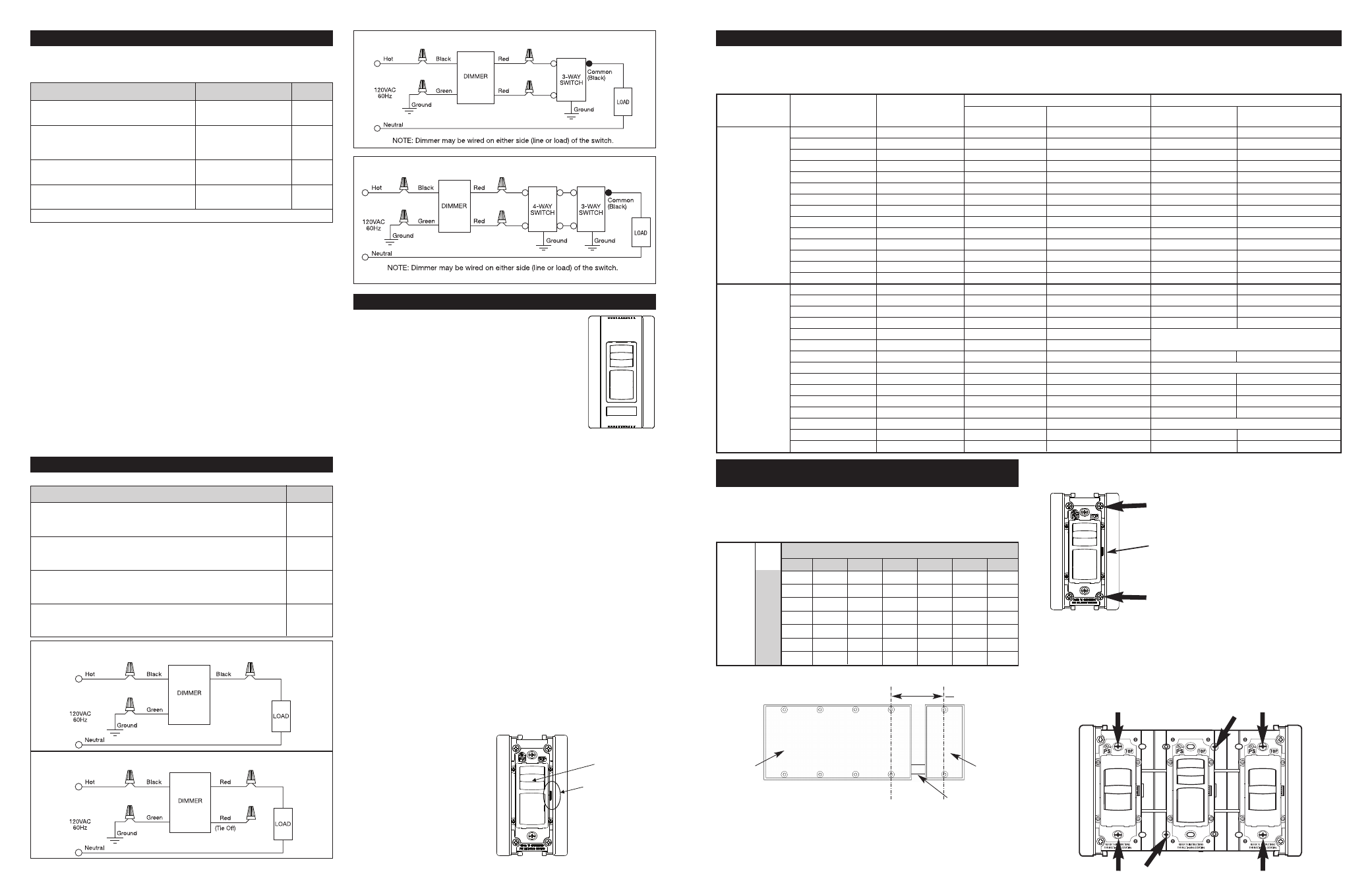
WIRING DIAGRAMS
Table 1
WIRING INFORMATION
IMPORTANT NOTES Read the following before installation:
• Requirements for wire strip length and wire connections.
WIRE NUT USAGE CHART
• Use a separate neutral wire for each phase of a multiphase system
containing a dimmer, and for high power single phase applications where
flickering is present.
• All dimmers can be damaged by improper wiring. Check for short circuits
prior to installing the dimmer.
Procedure for short circuit check:
a. Disconnect power to the circuit by removing fuse or turning circuit
breakers OFF.
b. Install a switch instead of the dimmer. Turn the switch to the “on” position.
c. Turn power ON. If the circuit breaker trips, a short is present. If the light
fails to turn ON and OFF with the switch, the wiring may be incorrect.
d. Correct wiring, if necessary and retest.
e. Install the dimmer only after the light operates properly with the switch.
• Protect from dirt and dust. The dimmer can be damaged from
contaminates encountered during the construction process. If lighting is
required prior to the construction process completion, then a switch should
be temporarily installed in place of the dimmer. The dimmer should not be
installed until the construction process is complete.
• Any dimmer damaged by improper installation is not covered under warranty.
• It is normal for the dimmer to feel warm during operation.
• Cleaning Instructions: Wipe dimmer with a damp, clean cloth.
DO NOT clean the dimmer with chemicals or cleaning solutions.
SINGLE GANG INSTALLATION INSTRUCTIONS
1. Disconnect power to circuit by removing fuse or turn
circuit breakers OFF before installing.
2. For existing installations: Remove wall plate and
switch mounting screws, pull existing switch from wall
box. For new installations: Install a 1-gang wall-box.
3. Disconnect existing switch from circuit.
3-way installation: Identify the “COMMON” wire (wire
connected to the terminal marked common or odd
colored terminal). For “new” installation identify wire
connected to power source or to the load.
4. Connect dimmer as shown in the wire diagram with
appropriate sized wire connectors (see Table 1).
5. Install dimmer in wall box, with the word “TOP” up, using mounting screws provided.
6. Insert the label, attach the wall plate and restore power to the circuit.
7. Dimmer Set-up Adjustments:
a. Incandescent Dimmer: The Full ON voltage can be reduced to save energy
by reducing the Full ON light level. To change the Full ON light level, slide
the dimmer knob up to its full brightness. DISCONNECT POWER FROM
CIRCUIT, and remove the wall plate. Use a small insulated, screwdriver to
adjust the trim potentiometer. Turn down to decrease the Full ON light level.
b. Magnetic Low Voltage Dimmer: The minimum light level may need
adjustment for variations in low voltage transformers. To change the
minimum light level, slide the dimmer knob down to the lowest
brightness. DISCONNECT POWER FROM CIRCUIT, and remove the wall
plate. Use a small insulated, screwdriver to adjust the trim
potentiometer. Turn down to decrease the minimum light level.
c. Fan Speed Controls: The minimum fan speed level may need adjustment
for variations in fans. To change the minimum fan speed, slide the knob
down to the lowest level. DISCONNECT POWER FROM CIRCUIT, and
remove the wall plate. Use a small insulated, screwdriver to adjust the
trim potentiometer. Turn down to decrease the fan speed. Make certain
that the fan does not “stall” in any of the ON positions as overheating of
the fan may occur. DO NOT USE THE FAN PULL CHAIN TO CHANGE
SPEEDS AFTER THIS CONTROL IS INSTALLED. THE FAN PULL CHAIN
NEEDS TO REMAIN AT THE MAXIMUM SPEED.
d. Dehummer Fan Speed Controls: No adjustments required. Make certain
that the fan does not “stall” in any of the ON positions as overheating of
the fan may occur. DO NOT USE THE FAN PULL CHAIN TO CHANGE
SPEEDS AFTER THIS CONTROL IS INSTALLED. THE FAN PULL CHAIN
NEEDS TO REMAIN AT THE MAXIMUM SPEED.
e. Fluorescent Dimmer: The
minimum light level may need
adjustment for variations in
ballasts. To change the
minimum light level, slide the
dimmer knob down to the
lowest brightness. DISCONNECT
POWER FROM CIRCUIT, and
remove the wall plate. Use a
small insulated, screwdriver to
adjust the trim potentiometer.
Turn up to increase the
minimum light level.
Knob
Trim Potentiometer
NOTE: Never adjust
trim potentiometer
when circuit is live.
MULTI GANG INSTALLATION INSTRUCTIONS
FINS ARE NOT REMOVED
NOTE: A 3-gang Installation of Narrow Dimmers is shown and described
below. Any Combination of Wide and Narrow Dimmers will gang the same way.
1. Select the correct box size from Table 2.
Table 2 – Wall-box Gang Requirements – FINS are NOT REMOVED
NOTE: The End Cap that is not between dimmers does not get removed.
3. Connect the dimmer as shown in the wiring diagram using the appropriate
sized wire connectors.
4. With the word “TOP” up, install dimmer in the wall box using mounting
screws provided (leave mounting screws “finger tight” at this point).
5. Attach the Couplers between the Dimmers with the screws that were
removed in step 2.
Remove this screw to remove End Cap
End Cap
Remove this screw to remove End Cap
*Wall Box Requirements for Ganging an Even Number of Narrow Dimmers.
4+1 set up shown below:
Chase nipple
4-gang
wall box
1-gang
wall box
2.712
Narrow Dimmers
0
1
2
3
4
5
6
0
0
1
1+1*
4
4+1*
7
7+1*
1
1
3
5
6
8
9
11
2
4
5
7
8
10
11
13
3
6
8
9
11
12
14
15
4
9
10
12
13
15
16
-
5
11
13
14
16
–
–
-
6
14
15
–
–
–
–
W
id
e
D
im
m
er
s
Dimmer Catalog #
Diagram #
CD700, CD1100, CDLV700, CDLV1100, CD1600, CDLV1600,
CD2000, CDFB5, CDFB8, CDFB10, CDFB16, CDFB7-277,
1
CDFB10-277, CDDH16, CDSC6, CDSC12
For Single Pole Installation of: CD703P, CD1103P, CDLV703P,
CDLV1103P, CD1603P, CDLV1603P, CD2003P, CDFB53P, CDFB83P,
2
CDFB103P, CDFB163P, CDFB73P-277, CDFB103P-277
For 3-Way Installation of: CD703P, CD1103P, CDLV703P,
CDLV1103P, CD1603P, CDLV1603P, CD2003P, CDFB53P, CDFB83P,
3
CDFB103P, CDFB163P, CDFB73P-277, CDFB103P-277
For 4-Way Installation of: CD703P, CD1103P, CDLV703P,
CDLV1103P, CD1603P, CDLV1603P, CD2003P, CDFB53P, CDFB83P,
4
CDFB103P, CDFB163P, CDFB73P-277, CDFB103P-277
MULTIPLE GANGING OF DIMMERS
Any combination of dimmer models may be ganged together. Using a vise or heavy-duty pliers, remove the fins on either or both sides of the heat sink, as
necessary. Dimmers can be ganged without removing fins by proper selection and placement of outlet boxes (see Table 2 and
Table 3). When Dimmers are ganged, De-rate the maximum load according to the following De-Rating Table 1:
Table 1 – Derating for Multi-Gang Installations
2. Remove the End Cap between adjacent dimmers (2 screws for each End
Cap). Keep these screws as they will be needed at step #5.
Fins are NOT Removed
Fins are Removed
Dimmer
1-Gang
2-Gang
3- or more Gang
2-Gang
3- or more Gang
Catalog #
Installation
Installation
Installation
Installation
Installation
CD700
700W
700W
700W
700W
700W
CDLV700
700VA
700VA
700VA
700VA
700VA
CD703P
700W
700W
700W
700W
700W
CDLV703P
700VA
700VA
700VA
700VA
700VA
CD1100
1100W
1100W
1000W
1000W
900W
Narrow
CDLV1100
1100VA
1100VA
1000VA
1000VA
850VA
Dimmers
CD1103P
1100W
1100W
1000W
1000W
950W
CDLV1103P
1100VA
1100VA
1000VA
1000VA
850VA
CDFB5
5A
5A
5A
5A
5A
CDFB8
8A
8A
8A
7.7A
6.3A
CDFB53P
5A
5A
5A
5A
5A
CDFB83P
8A
8A
8A
7.7A
6.3A
CDSC6
6A
6A
6A
6A
6A
CDDH16
1.6A
1.6A
1.6A
1.6A
1.6A
CD1600
1600W
1600W
1600W
1600W
1550W
CDLV1600
1600VA
1600VA
1600VA
1600VA
1550VA
CD1603P
1600W
1600W
1600W
1600W
1550W
CDLV1603P
1600VA
1600VA
1600VA
1600VA
1550VA
CD2000
2000W
2000W
2000W
NO FINS TO REMOVE
CD2003P
2000W
2000W
2000W
Wide
CDFB10
10A
10A
10A
10A
10A
Dimmers
CDFB16
16A
16A
16A
NO FINS TO REMOVE
CDFB7-277
7A
7A
7A
7A
7A
CDFB10-277
10A
10A
10A
10A
10A
CDSC12
12A
12A
12A
12A
12A
CDFB103P
10A
10A
10A
10A
10A
CDFB163P
16A
16A
16A
NO FINS TO REMOVE
CDFB73P-277
7A
7A
7A
7A
7A
CDFB103P-277
10A
10A
10A
10A
10A
Wire Combinations
Strip Lengths
Color
1#14 & 1#16; 1#14 & 2#18; 2,3#16;
1/2" Except 9/16"
Orange
1#16 & 1-3#18; 3-5#18; 2#18
For #16 & #18 AWG
1#10 & 1#14; 1#12 & 1#14 2, 3#14;
1/2" Except 5/8"
Yellow
2#14 & 1,2#16; 2#14 & 2,3#18;
For #16 AWG
1#14 & 1-4#16; 1#14 & 1-4#18
1#10 & 1,2#12; 1#10 & 1-3#14; 2,3#12;
7/16" Except 1/2"
Red
1#12 & 1-3#14; 1#12 & 3#16; 3,4#14
For #16
1#14 & 1,2#16; 1#14 & 1,2#16;
7/16" For #14 & #16
Ivory
2,3#16; 2-5#18
1/2" For #18
Use Only Copper Wire With This Device.
DIAGRAM 1 (Single-Pole Wiring)
DIAGRAM 2 (Single-Pole Wiring Using 3-Way Preset Dimmer)
DIAGRAM 3 (3-Way Wiring)
DIAGRAM 4 (4-Way Wiring)