Unit description and operation, Coverage patterns, Installation – Legrand WSP-250 User Manual
Page 2: Wiring directions
UNIT dEScRIPTION aNd OPERaTION
The WSP‑250 Wall Switch Occupancy Sensors turn lighting or fan loads on and
off based on occupancy and ambient light level. They are designed to replace a
standard light switch. The WSP‑250 operates with 120 or 277VAC line voltage.
The sensor uses passive infrared technology to sense human motion, and
defines it as occupancy. A green LED on the sensor blinks upon occupancy and
then resets. It will blink again when it detects motion after the 2‑second reset.
The sensor turns on the load automatically when it detects occupancy. Once the
space is vacant and the time delay elapses, it turns off the load automatically.
If adequate ambient light is already present in the area, the sensor will hold
off the load it controls. When the light drops below a field selectable level and
the sensor detects occupancy, the sensor turns on the load. Once turned on,
the load remains on until the space is vacant or the light level rises above the
setpoint and the time delay expires.
manual Operation: The occupant can press the ON/OFF button to turn the load
on and off. When the load is turned off or on manually, it stays off or on as long
as the sensor detects motion. After no motion is detected for the length of the
time delay, the sensor goes back to automatic operation. If the load was on, it
turns off. The next time the sensor detects occupancy and the ambient light is
lower than the set level, the sensor automatically turns on the load.
Walk‑test feature:
When the Time Delay trimpot
is in the fully counterclockwise
position, the sensor has a 30
second time delay and the Light
Level function is disabled. This
allows you to quickly check the
sensor coverage area.
Override function:
In the event of unit failure or
if it is necessary to leave the
load on, remove the Override
Jumper plug. This disables all
automatic on and off functions
and the load can only be
operated using the ON/OFF
button.
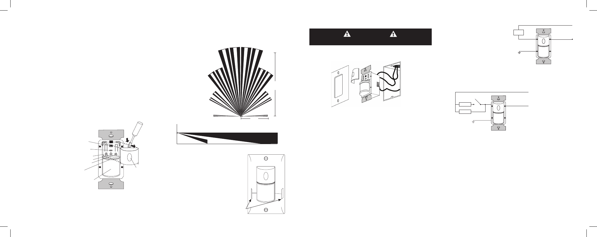
cOVERaGE PaTTERNS
The WSP‑250 detects motion in areas up to 900 sq. ft. and up to 35 feet from
the sensor. Ideally, the sensor is designed for small amounts of motion in
spaces up to 300 sq. ft. The Fresnel lens on the sensor is a multiple segment
viewing lens with a field of view of 180°.
The sensor must have a
clear view of the people in
the space in order to detect
occupancy. Obstructions,
such as furniture blocking
the sensor’s lens, may
prevent occupancy
detection.
15'
(4.6m)
35'
(10.7m)
4.0'
(1.2m)
35'
(10.7m)
floor
masking the lens
Opaque adhesive tape is supplied so that
sections of the sensor’s view can be masked.
This allows you to eliminate coverage in
unwanted areas.
Since masking removes bands of coverage,
remember to take this into account when
troubleshooting coverage problems.
1. Connect the existing wires in the wall box to the sensor flying leads.
(See Wiring Directions at right).
• Do not allow bare wire to show below connector.
• The ground wire must be tightly grounded for the unit to operate
properly.
2. Attach the sensor to the wall by mounting it in the wall box with the two
mounting screws provided.
3. Turn on power at the circuit breaker.
There is an initial warm‑up period after installation. It may take up to a
minute before the load turns on due to a sensor warm‑up period during
initial power‑up (this occurs during installation only). The load turns on after
the warm‑up period ends if the sensor detects motion.
Rapid successive pressing of the ON/Off button causes a delay in function.
A single press of the button causes an immediate response. If the button
is pressed again within 2 seconds, the switch ignores it. Wait at least two
seconds between button presses.
4. Test the sensor using the procedure in the Sensor Adjustments section.
5. Replace wall switch cover plate.
caUTION
Turn the power off at the circuit breaker before installing the sensor.
INSTaLLaTION
Cover plate
WSP-250
Wall Switch
Wall
Junction Box
Load
Red
Black to Line
Green
Neutral
Single‑level wiring
WIRING dIREcTIONS
For normal installation of the
WSP‑250 connect:
1. LOAD to Red flying lead.
2. LINE to Black flying lead.
3. GROUND to Green .
call 800.223.4185 for Technical Support
call 800.223.4185 for Technical Support
manual bi‑level lighting wiring
Load
Load
Green
Red
Black to Line
Neutral
Visit our website: www.passandseymour.com
Visit our website: www.passandseymour.com
ON/OFF
Switch
Override
Jumper
Light Level
Time Delay
Sensitivity
LED
Fresnel Lens
ON/OFF Button
(Switch Cover)
Press down
on tab and
pry off Cover
(L)
(T)
(S)
Maximum = clockwise
Minimum = counterclockwise
Side View
Top View
Opaque tape
WSP250 IS_340886 11343.indd 5-8
3/30/09 9:19:52 AM