Legrand 1220TWHB User Manual
Page 2
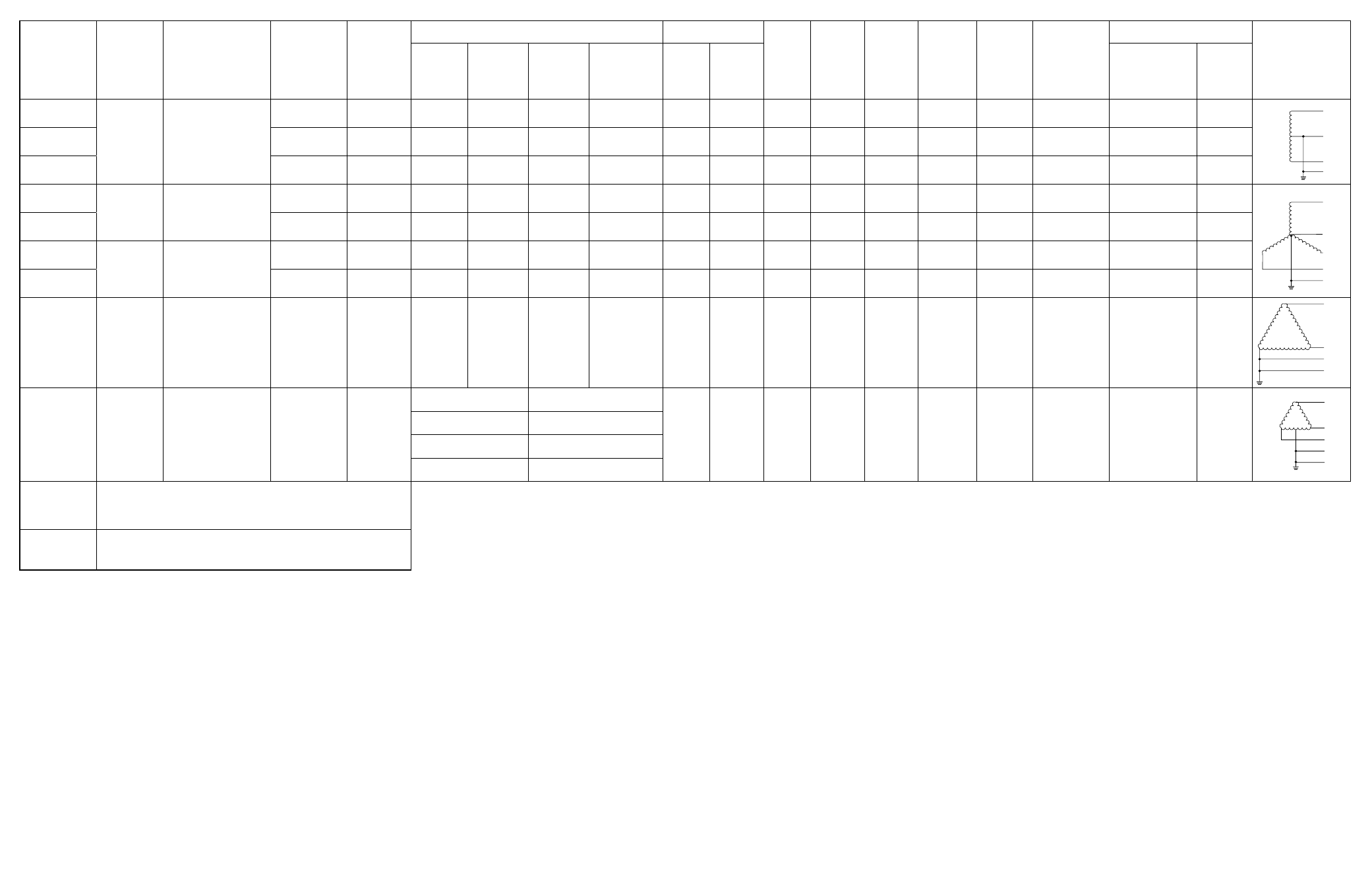
Catalog
Number
Nominal
Voltage
System
Application
Max Surge
Capability
Available
Interrupt
Current
UL 1449 Suppressed Voltage Ratings (Vpk)
Visual Indicators
Audio
Alarm
Alarm
Disable
Switch
Test
Switch
Form C
Contact
EMI/RFI
Filtering
Rotary
Disconnect
Connection Means
Transformer
Configurations
Line to
Neutral
Line to
Ground
Line to
Line
Neutral to
Ground
Red
Green
Type
Gauge
1224-SL
120VAC
Single Phase, 3W
plus Ground
40KA
42kAIC
400
N/A
700
N/A
0
2
X
Wire
10
1224-SM
100KA
65kAIC
400
800
800
400
1
2
X
X
X
Wire
12
1224-SH
200KA
200kAIC
400
400
700
400
1
1
X
X
X
X
X
X
Screw Terminal
1/0 – 14
1220-TWM
120/
208VAC
Three Phase, Wye,
4W plus Ground
100KA
65kAIC
400
800
800
400
1
3
X
X
X
Wire
12
1220-TWH
200KA
200kAIC
400
400
700
400
1
1
X
X
X
X
X
X
Screw Terminal
1/0 – 14
2748-TWM
277/
480VAC
Three Phase, Wye,
4W plus Ground
100KA
65kAIC
800
1500
1500
800
1
3
X
X
X
Wire
12
2748-TWH
200KA
200kAIC
700
700
1500
700
1
1
X
X
X
X
X
X
Screw Terminal
1/0 – 14
480-TDH
480VAC
Three Phase,
Delta, 3W plus
Ground
200KA
200kAIC
N/A
1500
1500
N/A
1
1
X
X
X
X
X
X
Screw Terminal
1/0 – 14
240-TDM
120/
240VAC
Three Phase,
Delta, High Leg,
4W plus Ground
100KA
65kAIC
A-N,C-N: 400
B-N:
800
1
3
X
X
X
Wire
12
A-G,C-G: 800
B-G:
1500
N-G:
400
A-B:
1500
A-C:
800
B-C: 1500
RSKIT
Operates from 120VAC. Interfaces with any of the above
surge suppressors available with the
“Form C Contact” option.
MFKIT
Allows for flush mounting of Catalog Numbers 1224-SM,
1220-TWM, 2748-TWM, 240-TDM.
nominal Voltage – this is the nominal line to neutral or line to line voltage
that the surge suppressor is intended to be connected to. Failure to match
surge suppressors to nominal system source voltages can permanently
damage the device or provide inadequate surge suppression.
system application – the electrical transformer source configuration the
surge suppressor was designed to be connected to.
maximum surge capability – the maximum surge current the device can
withstand non-repetitively without a change in measured limiting (clamping)
voltage of more than plus or minus 10%. This number is also a reflection
of the number of lower current pulses the device can withstand without a
change in measured limiting voltage. The higher this number is the more
lower current transients the device can withstand.
Available Interrupt Current (AIC) – the highest current at rated voltage
that a device is intended to interrupt under standard test conditions.
(NEMA Surge Protection Institute)
ul1449 suppressed Voltage rating – Underwriters Laboratories Standard
1449, “Transient Voltage Surge Suppressors,” contains a section that man-
dates the measurement of let-through (clamping) voltage under a certain
repeatable transient condition, for each mode in which surge suppression
is claimed. This allows for comparison among various manufacturers of
let-through voltage in a way that is meaningful to the end user.
Visual indicators – provides a method for determining the status of the
surge suppression components. When all surge suppression components
are operational, the green lights will be lit and the red light (if provided) will
be off. Loss of surge suppression in any mode will cause a green light or
lights to go out and the red light to come on. Periodic monitoring of these
status indicators is necessary to insure prompt replacement of surge
suppression in case of failure.
audio alarm – provides supplementary indication of failed surge suppres-
sion components. The alarm will sound whenever surge protection is lost.
alarm Disable switch – this switch has two positions. The “enable”
position allows the alarm to sound upon loss of surge protection. The
“disable” position turns the alarm off if protection has been lost, or inhibits
the alarm from sounding if this position has been selected prior to failure of
surge suppression components.
Test switch – allows for operational testing of the red indicator light and the
audio alarm. Pressing this switch will turn the red light on and energize the
audio alarm if alarm disable switch is set to enable.
form c contact – provides a normally open, normally closed, and common
set of contacts for use with RSKIT, or for other user defined functions. The
relay that controls these contacts is energized when all surge suppression
components are functional. It will deenergize upon loss of protection.
emi/rfi filtering – provides for a degree of protection against conducted
radio frequency and electromagnetic noise present on electrical power
distribution wiring. Attenuation levels up to 40db are possible between
frequencies of 100KHz and 30MHz.
rotary Disconnect – allows for removal of electrical power in the event that
servicing is required.
connection means – required type of electrical connection to the surge
suppressor. If the connection requirement is for screw terminal, the allow-
able wire gauges are shown.
Transformer configurations – pictorial representation of the transformer
configuration the surge suppressor is intended to be connected to.
L1
L2
A
N
B
C
G
A
B
C
G
B
C
A
N
G
N
G
L1
L2
A
N
B
C
G
A
B
C
G
B
C
A
N
G
N
G
L1
L2
A
N
B
C
G
A
B
C
G
B
C
A
N
G
N
G
L1
L2
A
N
B
C
G
A
B
C
G
B
C
A
N
G
N
G