Is-0357 rev. a – Legrand HT1000 User Manual
Page 2
INSTRUCTION / INSTALLATION SHEET
Home Entertainment Connection
Center (HECC 7.1)
IS-0357 Rev. A
301 Fulling Mill Road, Suite G
Middletown, PA 17057
Phone (800) 321-2343 / Fax (717) 702-2546
www.onqlegrand.com
©Copyright 2007 by On-Q/Legrand All Rights Reserved.
Page 2 of 3
2) One RG6QS cable should be run from a single gang outlet box or mud ring at the desired sub-woofer location to the HECC location,
leaving extra cable at both ends.
NOTE: The number of speaker wire runs will vary depending upon which theater format is being utilized.
3) At least one RG6QS cable and two Cat 5e cables should be run in the wall from the HECC location to the structured wiring
enclosure, leaving extra cable at both ends. Clearly label each cable as it is installed.
NOTE: The RG6QS cable is for normal distributed TV service. If Satellite service is planned, additional cables may need to
be run. The two Cat 5e cables are for phone and data services.
4) 6 Room Audio pre-wire (if applicable): run 16/4 or 14/4 high quality speaker wire from the HECC location to the volume control
locations and 16/2 or 14/2 from the volume control locations to each speaker location, leaving extra cable at both ends. Clearly label
each cable as it is installed.
5) lyriQ™ pre-wire (if applicable): run Cat 5e cable from the HECC location to the structured wiring enclosure, leaving extra cable at
both ends. Clearly label each cable as it is installed. Complete pre-wire of lyriQ™ system per lyriQ™ instructions.
NOTE: Always mark cables at both ends for easy identification at trim-out.
"Trim-out" Steps
A. At the HECC location, pull the RG6QS and speaker wires through the HECC mounting
bracket. Terminate the RG6QS cables with "F" connectors and attach to the appropriate
connectors for distributed TV service and sub-woofer service. The Surround Sound speaker
wires should be terminated at the screw terminals on the back of the HECC in accordance with
the appropriate speaker locations (5.1, 6.1, 7.1) as indicated on the HECC (see Figure 4).
NOTE: Follow this pattern for proper surround sound speaker connections to the User
side (5,5,5,5,5,6,7,.1): A) for 5.1 connect wires to connectors labeled "5" and ".1", B) for
6.1 connect wires to connectors labeled "5" and "6" and ".1", C) for 7.1 connect wires
to connectors labeled "5" and "6" and "7" and ".1"
Surround sound speakers are usually mounted on the sides of the room and not the
rear. For 5.1, the left and right speakers would be mounted on the left and right hand
sides. For 6.1, the speakers would be mounted on the left and right sides and the 3rd
speaker would be mounted in the center rear. For 7.1 the speakers would be mounted
on the left and right sides and the two additional speakers mounted in the left rear and
right rear positions (see Figures 5,6,7). In many situations it is necessary or desired to
substitute rear positions for the normally side mounted surrounds.
B. If using phone and data, terminate the Cat 5e cables from the structured wiring enclosure on the
universal Keystone RJ45 Jack Inserts and snap them into the back of the HECC.
C. Terminate any RG6QS cables with "F" connectors and attach them to the "F" feed through Inserts on the back of the HECC.
D. If using a 6 Room Audio Module, terminate the speaker wires from the impedance matching volume controls at the screw terminals on
the back of the HECC (see Figure 4).
E. If using a lyriQ™ system, terminate the Cat 5e cable from the structured wiring enclosure on a universal Keystone RJ45 Jack Insert and
snap the Insert into the back of the HECC. Using an RJ45 Jumper cable, such as P/N 363201-27, connect the lyriQ™ Source Input jack
labeled 'Audio Out' to the RJ45 jack which carries the lyriQ™ line level signal to the structured wiring enclosure.
F. Once all cables are attached to the back of the HECC, secure the HECC insert to the HECC mounting bracket using 4 drywall screws.
G. If using 6 Room Audio module, terminate the left and right speaker wires from the audio amplifier at the Source In connectors on the 6
Room Audio Module, using 16/4 high quality speaker wire.
NOTE: Impedance matching volume controls must be used to protect the audio source equipment.
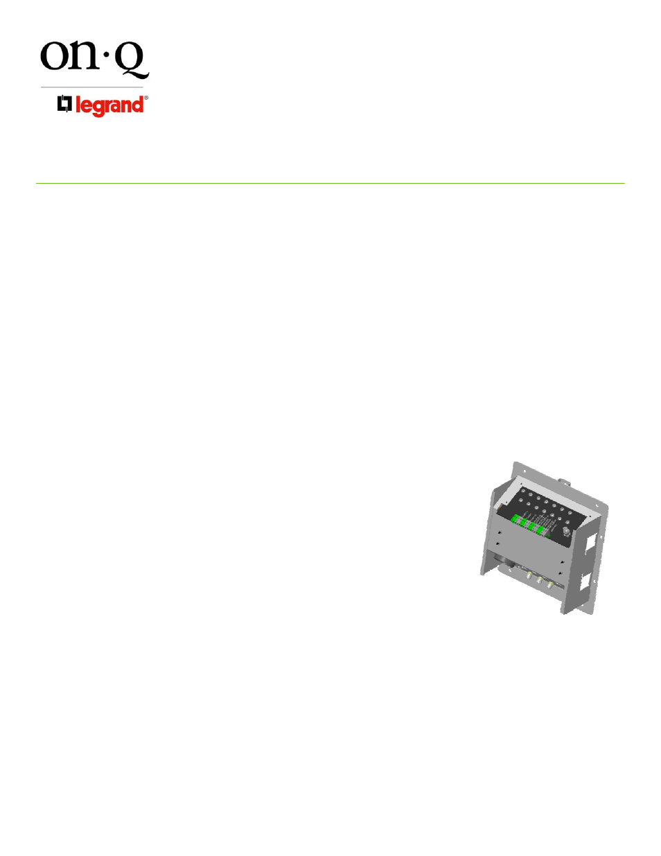
Figure 4