Operation – Legrand ASTM2 User Manual
Page 2
No: 340976 – 04/26 Rev. 1
© Copyright 2012 Legrand All Rights Reserved.
60 Woodlawn Street
West Hartford, CT 06110
1.877.BY.LEGRAND
(295.3472)
www.legrand.us
570 Applewood Crescent
Vaughan, ONT L4K 4B4
905.738.919 5
www.legrand.ca
TOP
60
30
20
10
60
30
20
10
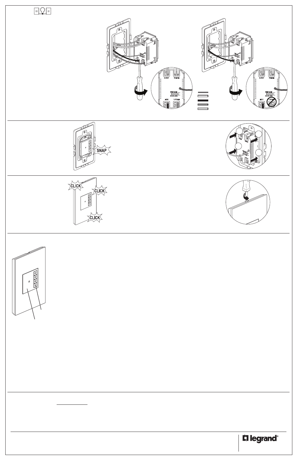
NOTE – If you need to remove switch after snapping into frame,
first remove frame from wall box to access the four locking tabs
on the back of the switch. Insert a flat screwdriver to depress
tabs as you apply pressure to push sensor out.
NOTE – To remove wall plate, insert a small, flat
screwdriver in notches on wall plate and twist gently
to pry from frame.
4
5
Carefully fold wires into box.
Snap switch into frame.
6
STRIPG
AGE
AY
WAA
WA
W
WA
3-W
AY
-W
3-W
3--
3-W
3333333
WHITE
1
2
3
4
Snap wall plate to frame.
There are three click-stops to
adjust the fit of the wall plate
to the switch and the wall.
Never apply cleaner directly to the switch or wall plate.
Apply to a soft cloth and use cloth to remove any smudges
from the product.
Technical Assistance:
(877) 295-3472
www.adornemyhome.com/install
LIMITED LIFETIME WARRANTY
Limited lifetime warranty information for adorne products is available at
www.adorne.com/warranty. Limited warranty information for adorne
TM
products may also be obtained free of charge by sending a written
request, along with your proof of purchase (including purchase date), to:
Legrand
Attn: adorne Customer Service/Warranty Department
50 Boyd Avenue
Syracuse, NY 13209
3-Way
The term master designates the sensor that connects
to the load. The term auxiliary refers to the sensor that
does not connect to the load.
Master
• Connect NEUTRAL wire from the circuit and from the
lamp (LOAD) to WHITE terminal
• Connect LINE wire to HOT terminal
• Connect LOAD wire to 1-POLE terminal
• Connect TRAVELER wire to the 3-WAY terminal
NOTE: NEUTRAL wire is not required for
sensor to function properly.
Auxiliary
• Connect NEUTRAL wire from circuit in the other wiring
box to WHITE terminal
• Connect LINE wire to HOT terminal
• Connect TRAVELER wire to the 3-WAY terminal
• 1-POLE terminal on auxiliary is not used
NOTES: A light can be controlled by one master and
up to four auxiliary sensors.
If you are installing multiple sensors in the frame,
wire all devices before snapping them into the frame.
The adorne SensaSwitch - Manual ON/Timed OFF turns OFF the
connected light when the selected time expires.
Manual-On
Turn ON the connected light by pressing the desired preset time
button or the ON/OFF button. If you press the ON/OFF button, it acti-
vates the time that was last used.
Manual-off
While a timer is active, you can press the ON/OFF button to turn OFF
the connected light without delay.
Changing the selected time
If you decide that you need more or less time than you originally
selected, restart the time switch by pressing the button that matches
the amount of time you think you will need.
LED functionality
The time switch has one locator LED on the ON/OFF button and each
preset time button has an integral LED to illuminate the numbers on
the preset time buttons. When the connected light is off the locator
LED will be on. When the connected light is on the preset time button
that was pressed will be illuminated and the locator LED will be off.
The preset time buttons will also function as a rough countdown
timer. For example when you select 30 minutes, the 30 minute
preset time button will be illuminated until 21 minutes remain in the
countdown. At this point the 30 minute button will start to slowly flash
for the next minute until 20 minutes are left in the countdown. Once
20 minutes are left, then the 20 minute preset button will become
illuminated and the 30 minute button will turn off.
Disabling the locator LED
The locator LED can be disabled by pressing and holding the on/off
button for 10 seconds. After 10 seconds the locator LED will flash to
indicate that the locator LED has been disabled. To enable the LED,
press and hold the on/off button for 12 seconds. The locator LED will
flash at 10 seconds, continue holding down the on/off button until the
locator LED flashes twice at 12 seconds indicating that the LED has
been enabled.
60
30
20
10
Preset Time Buttons
On/Off Button
Note: The LEDs will only function when the neutral wire is connected.
When the neutral wire is not connected the device will function
properly, but the locator LED and preset time button LEDs will never
be illuminated. See Step 4 above for details on how to wire the device.
TROUBLESHOOTING
To test the time switch:
If the neutral wire is connected, the locator LED should be ON when
the switch is OFF (as long as the locator LED has not been disabled.
See above.)
Press the ON/OFF button. The connected light turns ON. The
connected light should turn off in the number of minutes indicated
by the preset time button. You can turn the light OFF sooner by
pressing the ON/OFF button again.
Status LED is enabled and the load will not turn ON:
• Check the lamp to make sure that it has not burned out
• Turn OFF power to the circuit to check the wire connections
No Status LED:
• Check the ground and neutral connections (note: neutral is not
required for product to function properly)
Light will not turn OFF:
• Make sure there is a solid ground connection. The device requires
the ground connection to operate
• Press the ON/OFF button. If connected light or fan does not turn
OFF, turn OFF power to the circuit then check wire connection.
Factory reset
To change the operating mode back to the default settings press and
hold the on/off button for 15 seconds. The locator LED will flash once
at 10 seconds, continue to press and hold the on/off button. The
locator LED will flash twice at 12 seconds, continue to press and hold
the on/off button. The locator LED will flash 3 times at 15 seconds
signaling that the device has been reset.
OPERATION
1-POLE
3-W
AY
WHIT
E
HOT
AY
AY
W
W
1-POLE
STRIP
3-W
AY
WHIT
E
HOT
P
W
W
3
3
3-Way Master
3-Way Auxiliary
1-POLE
STRIP GAGE
3-WAY
WHITE
HOT
1-POLE
STRIP GAGE
3-WAY
WHITE
HOT
1-POLE
3-W
AY
WHIT
E
HOT
AY
AY
W
W
1-POLE
STRIP
3-W
AY
WHIT
E
HOT
P
W
W
3
3
1-POLE
STRIP GAGE
3-WAY
WHITE
HOT
1-POLE
STRIP GAGE
3-WAY
WHITE
HOT
Ground
Neutral
Hot/Line
Load
Traveler