Legrand RWDU500 User Manual
Page 2
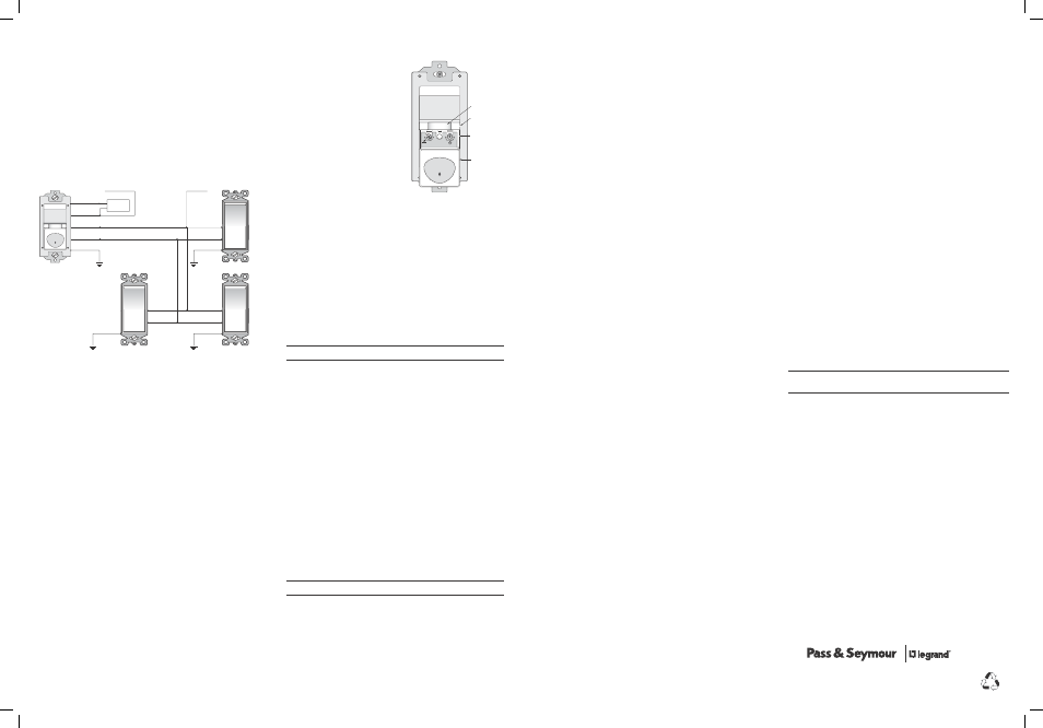
4c: Multi-way wiring using one RWDU500 and up to four TM870STMs:
One RWDU500 can be connected with up to 4 TM870STM single pole momentary
wall switches for multi-way Manual-ON/OFF control of one single load. The
RWDU500 must be installed in the wiring wall box that connects to the load.
Connect the existing wires to the wire leads on the RWDU500 sensor as indicated
below (See Fig. 4c). Cap them securely using wire nuts provided.
• Connect the green or non-insulated (copper) GROUND wire from the circuit to
the green wire on the RWDU500.
• Connect the NEUTRAL wire from the circuit and from the lamp (LOAD) to the
white wire on the RWDU500.
• Connect the power wire from the circuit box (HOT) to one terminal on each
TM870STM single pole momentary wall switch and to the TRAVELER 1 wire.
• Connect the TRAVELER 1 wire coming from each TM870STM wiring box to the
black wire of the RWDU500.
• Connect the lamp power (LOAD) to the red wire on the RWDU500.
• Connect the TRAVELER 2 wire to the other side of each TM870STM single pole
momentary wall switch and to the yellow wire of the RWDU500.
Red
Ground
Yellow
Black
White
Load
Traveler 2
Hot
Neutral
Traveler 1 (Hot)
TM870STM
TM870STM
Ground
TM870STM
Ground
Ground
Traveler 2
Traveler 1
Traveler 2
Traveler 1
Traveler 2
Traveler 1
RWDU500
Fig. 4c: Multi-way wiring using one RWDU500 and three TM870STMs
5. Put the RWDU500s (and TM870STMs if applicable) into their respective
wall boxes.
Position them with the lens positioned above the ON/OFF/DIM button (lens at
top, ON/OFF/DIM button at bottom). Secure to the wall box with the screws
provided.
6. Make any necessary adjustments.
See the SENSOR ADJUSTMENT &PROGRAMMING section for information.
7. Attach the new cover plate.
Secure it with the screws provided.
8. Restore power to the circuit.
Turn on the breaker or replace the fuse.
INITIAL POWER-UP DELAy & CALIbRATION
There is an initial warm-up and calibration period the first time power is applied
to the unit, after a power failure lasting more than 5 minutes and after the
dimming load is replaced. If the sensor is in Mode 2, (automatic-ON) it may take
up to 1 minute before the lights turn ON. However, the lights can be turned ON/
OFF and dimmed manually by pressing the ON/OFF/DIM button at any time when
power is supplied to the unit.
Load Calibration: The RWDU500 calibrates its dimming range to the load’s
wattage rating by briefly dimming the load up and down from its minimum output
(approx. 10%) to its maximum.
SENSOR ADJUSTMENT & PROgRAMMINg
To adjust the RWDU500, you use controls
located under the ON/OFF/DIM button. The
wall switch cover plate must be removed
to gain access to the mode button and
adjustment dials under the ON/OFF/DIM
button.
Note: For multi-way operation of two or
more RWDU500s, it is recommended to set
to the same values the Operating Mode and
the Time Delay adjustments in all sensors
related to the same load.
1. Firmly grasp the side edges of the Lock
Bar and gently pull it away from the
switch face until it clicks. Do NOT attempt
to pull the Lock Bar off of the switch!
2. Firmly grasp the side edges of the
ON/OFF/DIM button. Slide the button
downward approximately 1/2 inch
to expose the mode button and
adjustment dials.
Setting up the Operating Mode
Select the operating mode by pressing the Mode button. The green LED behind
the switch button blinks to indicate the selected mode:
• One blink indicates Mode 1 (Vacancy Sensor Operation), Manual-ON/OFF,
Auto-OFF
• Two blinks indicate Mode 2 (Occupancy Sensor Operation), Auto-ON/OFF with
manual control and reset to auto (after 5 minutes of vacancy).
To change the operating mode, press the Mode button. The LED blinks to indicate
the selected mode. It repeats the selected mode three times. After that, the unit
operates in the indicated mode.
Adjusting the Time Delay
Turn the right dial counter-clockwise to reduce the amount of time the lights
will remain on after the last motion detection (minimum = 15 seconds). Turn the
same dial clockwise to increase this time delay (maximum = 30 minutes). You can
only select the following values: 15 seconds/5 minutes/15 minutes/30 minutes.
Warning: Do not overturn the Time Delay adjustment dial!
Adjusting the Light Level
This feature is factory set at maximum, so that even the brightest light will not
prevent the sensor from turning the load ON when it detects occupancy. If this
feature is not needed, leave the light level at maximum, fully clockwise. The light
level must be adjusted when lights would normally be turned OFF because there
is enough natural illumination. Each RWDU500 may have a different light level
setting.
1. Set all RWDU500s to Mode 1 (Manual-ON) - except for the one that you’re
adjusting.
Set the RWDU500 you’re adjusting so that it is in Mode 2 (Automatic-ON).
2. Reduce the time delay to 15 seconds.
3. Adjust the Light Level dial to minimum (fully counter-clockwise) on the unit
that you’re adjusting. Move out of the coverage area. Let the sensor time out
so lights are OFF and then wait 30 seconds more.
4. Without casting a shadow on the sensor, enter the area. The lights should
remain OFF. Adjust the Light Level dial clockwise in small increments. After
each adjustment, wait 5-10 seconds to see if the lights turn ON.
Continue this procedure until the lights turn ON. At this setting the light will
not turn ON automatically with occupancy if the light level measured at this
sensor is above the current natural illumination.
5. Repeat the process (beginning with step 1) for each RWDU500 in your
multi-way configuration until the Light Level has been adjusted properly in
all of them.
6. When you have finished adjusting the Light Level of all the RWDU500s, return
them all to Mode 2.
7. Reset the time delay to the desired setting in all units.
Warning: Do not overturn the Light Level adjustment dial!
WARRANTy INFORMATION
Pass & Seymour/Legrand warranties its products to be free of defects in
materials and workmanship for a period of five (5) years. There are no obligations
or liabilities on the part of Pass & Seymour/Legrand for consequential damages
arising out of, or in connection with, the use or performance of this product or
other indirect damages with respect to loss of property, revenue or profit, or cost
of removal, installation or reinstallation.
P.O. Box 4822, Syracuse, NY 13221-4822
Technical Support: 800.223.4185
www.passandseymour.com
340898 11049
Please
Recycle
TEST MODE
To test the detection coverage:
1. Press and hold the ON/OFF/DIM button. After 10 seconds the lighted switch
turns off. The load turns ON if it was not already ON. The sensor is now in
a TEST mode that lasts 5 minutes. (You can end the TEST mode sooner by
pressing the ON/OFF/DIM button for another 10 seconds).
During the TEST mode, the controlled load turns ON for 5 seconds each time
the sensor that initiated the TEST mode detects occupancy.
2. Move out of the coverage area or stand very still. The controlled load turns OFF
after 5 seconds if no motion is detected.
3. Move into the coverage area for the unit that initiated the TEST mode. The
controlled load turns ON for 5 seconds each time the sensor detects motion.
After 5 seconds expire without motion detection, the load turns OFF. The
controlled load turns ON automatically with the next motion detection and
stays ON for 5 seconds.
4. Repeat as necessary to ensure that the desired coverage areas are within
detection range.
You can do this test for each RWDU500 in your multi-way configuration. So
that you can determine the actual coverage area for each multi-way switch
individually, only the RWDU500 that is in TEST mode will control the load.
REPLACINg LAMPS
When replacing a bulb in a lamp connected to an RWDU500, use the Air Gap
Isolation feature for safety. If you have more than one RWDU500 controlling one
or various loads in a multi-way wiring configuration, apply the instructions below
to all RWDU500s for safety.
1. Push in the Air Gap Switch shown in Figure 5 so that it clicks and locks
into a depressed position below the surface of the rest of the RWDU500.
This engages the Air Gap, which stops electricity from flowing to the
connected load.
2. After replacing the bulb(s), press the Air Gap Switch so that it returns to a
position that is flush with the surface of the rest of the RWDU500. This allows
the dimming sensor to control the lighting load correctly.
3. The RWDU500 then calibrates its dimming range to the load’s wattage rating
by briefly dimming the load up and down from its minimum output (approx.
10%) to its maximum.
Lock Bar
Mode Button
& Adjustment
Dials
Slide down
On/Off/Dim
Button
Air Gap Switch
Time Delay
30
M
in
.
S
ec
.
15
Min.
5
Min.
m
ax
m
in
Mode
15
Light
Level
06006r1
1- Manual
2- Auto-ON
Fig. 5: Sensor Adjustment Controls
TROUbLESHOOTINg
Check the position of the Air Gap Switch on all RWDU500s before beginning
troubleshooting.
Lighted switch is OFF, no load response to pressing ON/OFF/DIM button(s) or
any of the TM870STM momentary wall switches (if applicable):
• Make certain that the circuit breaker is on and functioning.
Lighted switch is ON, no load response to pressing ON/OFF/DIM button(s) or
any of the TM870STM momentary wall switches (if applicable):
• Check the controlled dimmable lighting load(s) (light bulbs). Make sure that
the load(s) connected to the RWDU500s is (are) between 25- 500 watts.
• The lighting load(s) may not appear to be ON if the last used dimming level
was very low. To verify if this is the case, firmly tap the ON/OFF/DIM button
one time. The green LED should turn off. Next, press and hold the ON/OFF/
DIM button to turn UP the lighting level. If the lights do not get brighter, call
technical support.
Load will not turn ON automatically when the area is occupied and the sensors
are in Mode 2 (lighted switch is ON):
• Press ON/OFF/DIM button(s). If the load turns ON, check the Light Level
setting. The light level can prevent the sensor from turning ON the load
automatically. Make sure the sensor lenses are not blocked and that you are
within the coverage area of at least one sensor.
• If the load does not turn ON when you press the ON/OFF/DIM button(s), check
the dimmable lighting load(s). Make sure that the load connected to the
RWDU500(s) is between 25-500 watts.
• The lighting load may not appear to be ON if the last used dimming level was
very low. To verify if this is the case, firmly tap any ON/OFF/DIM button one
time. The green LED should turn off. Next, press and hold the same ON/OFF/
DIM button to turn UP the lighting level. If the lights do not get brighter, call
technical support.
• If the load(s) does (do) not turn ON when you press the ON/OFF/DIM button,
check the light bulb.
Load will not turn OFF automatically:
• Press the ON/OFF/DIM button. If the controlled load turns OFF, go to next step.
• The time delay can be set from 15 seconds to 30 minutes. Check the time
delay setting for each RWDU500 in your multi-way configuration. Ensure
that all RWDU500s have the same time delay setting. Ensure that there is
no movement within any of the sensors’ view for the set time period. Hot air
currents and heat radiant devices can cause false detection. Make sure the
sensor is at least 6 feet (2 meters) away from devices that are a significant heat
source (e.g., heater, heater vent, high wattage light bulb).
If load does not respond properly after following troubleshooting, turn OFF
power to the circuit then check wire connections or call technical support.
Call 800.223.4185 for Technical Support
www.passandseymour.com
Call 800.223.4185 for Technical Support
340898 11049_RWDU500 IS.indd 5-8
9/3/09 10:34 AM