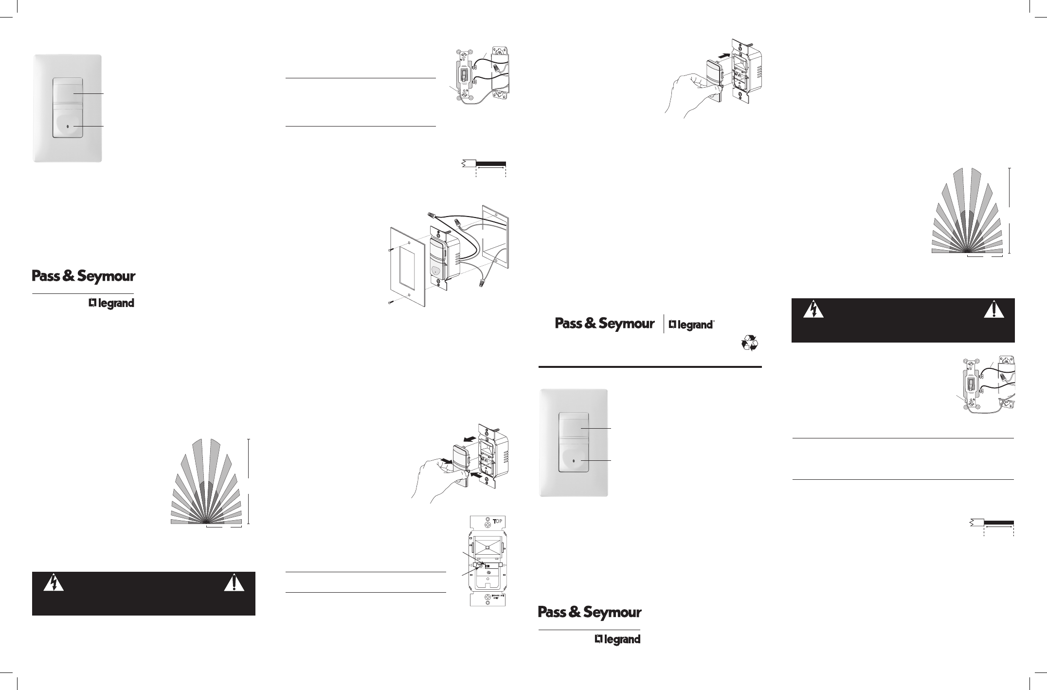
Legrand RW600B User Manual
Sensor de desocupación, Rw600b vacancy sensor switch, Rw600b
2. Identify the type of circuit.
In a Single Pole Circuit (see Fig. 2), two single wires
connect to two screws on the existing switch. A ground
wire may also be present and connected to a ground
terminal on the old switch.
CAUTION
For your safety: Connecting a proper ground to the
sensor provides protection against electrical shock
in the event of certain fault conditions. If a proper
ground is not available, consult with a qualified
electrician before continuing installation.
Only connect the RW600B to a Single Pole Circuit. The
RW600B is not suitable for 3-way switching. If the existing wiring does not match the
description for a Single Pole Circuit, you should consult with a qualified electrician.
3. Prepare the Wires.
Tag the wires currently connected to the existing switch, so
that they can be identified later. Disconnect the wires. Make
sure the insulation is stripped off the wires to expose their
copper cores to the length indicated by
the “Strip Gage,” in Fig. 3 (approximately 1/2 inch).
4. Wire the sensor.
Twist the existing wires together
with the wire leads on the RW600B
sensor as indicated below. Cap
them securely using the wire nuts
provided. See Fig 4.
• Connect the green or non-insulated
(copper) GROUND wire from the
circuit to the green ground wire on
the RW600B. Make sure there is a
solid ground connection.
• Connect the power wire from the
circuit (HOT) to the black wire on
the RW600B.
• Connect the power wire to the lamp
or fan (LOAD) to the red wire on the
RW600B.
5. Put the RW600B in the wall box.
Position the lens above the ON/OFF button (lens at top, button at bottom). Secure it
to the wall box with the screws provided.
6. Make any necessary adjustments.
See the SENSOR ADJUSTMENT section for
information.
7. Attach the new cover plate.
8. Restore power to the circuit.
Turn on the breaker or replace the fuse.
INITIAL POWER UP DELAY
There is an initial warm-up and calibration period the first time power is applied to the
unit after a power failure lasting more than 5 minutes, and after the load is replaced.
SENSOR ADJUSTMENT & PROGRAMMING
To adjust the RW600B, use controls located under the front
cover (lens and ON/OFF button). The wall switch wallplate
must be removed to gain access to the adjustment dial
under the ON/OFF button.
1. Remove the wallplate.
2. Firmly grasp the edges of the front cover
directly below the lens where it says “open”
(see Fig. 5). Push in one side first until it
pops out, then the other side. Remove front
cover from the unit.
Adjusting the Time Delay
The factory setting for the time delay dial is fully clockwise,
providing the maximum delay of 30 minutes. To reduce the
amount of time the load remains ON after the last motion
detection, turn the dial counterclockwise (minimum = 30
seconds). You can set the following times: 30 minutes, 20
minutes, 10 minutes, 5 minutes, 30 seconds.
CAUTION
Do not overturn the time delay adjustment dial.
Status LED
The small slide switch located to the right of the dial (see Fig.
6) enables and disables the Status LED indicator light on the
ON/OFF button. The factory default setting is enabled. When
enabled the Status LED blinks when the sensor detects motion, whether the load is ON
or OFF. To disable the blinking LED, move the slide switch to the right toward “OFF.”
CHANGING THE COLOR OF THE UNIT
1. Remove the wallplate
2. Firmly grasp the edges of the front cover directly below
the lens where it says “open.” Push in one side first
until it pops out, then the other side. Remove
front cover from the unit (see Fig. 5).
3. Take the new color front cover, place the top
peg in first then snap in each side one at a
time (see Fig. 7).
TROUBLESHOOTING
Status LED is enabled but not blinking and the load will not turn ON:
• Check the circuit breaker to be sure it is functioning.
Load will not turn ON:
Press ON/OFF button. The load should turn ON. If not:
• Check the light bulb and/or motor switch on the fan mechanism.
• Turn off power to the circuit then check wire connections.
Load will not turn OFF:
Note: The time delay can be set from 30 seconds to 30 minutes. Ensure that the time
delay is set to the desired delay and that there is no movement within the sensor’s view
for that time period.
• To quickly test the unit for proper operation, turn the time delay to minimum and
move out of the sensor’s view. Lights should turn off after 30 seconds.
• Press the ON/OFF button. If load does not turn off, turn off power to the circuit then
check wire connections.
• If load still does not turn off call 800.223.4185 for technical support
Green -> GROUND
Black -> HOT (power
from circuit box)
Time
Delay
Motion Blin
k
OFF
30sec.
30mi
n.
5min.
10m
in.
20m
in.
11543r
1
Red -> LOAD (power
to lamp or fan)
OPEN
Fig 4: Sensor orientation, wire connections
and wall box assembly
Ground
HOT (power from
circuit box)
LOAD
(power
to lamp)
NEUTRAL
Fig 2: Typical Single Pole
Switch Wiring
Strip Gage
1/2"
12.7mm
Fig 3: Wire Stripping
DESCRIPTION AND OPERATION
The RW600B Vacancy Sensor is designed to replace a standard light or fan switch. The
sensor uses passive infrared technology to sense human motion in a space and turn the
light OFF when the room is vacant. It is ideal for applications in a home where there is
a direct line of sight from the sensor to the room including bedrooms and family/living
rooms.
Like a standard switch, pressing the ON/OFF button will turn the light or fan (controlled
load) ON and OFF. Unlike a standard switch, the RW600B automatically turns OFF the
controlled load after the coverage area has been vacant for a period of time known as
the Time Delay. If motion is detected within 30 seconds after it automatically turns OFF,
the RW600B automatically turns the load back ON.
Indicator Light
The Status LED located on the ON/OFF button blinks
upon initial detection. It will blink again when it
detects a change of infrared energy in the space.
The LED can be disabled. See Status LED.
Coverage Area
The RW600B has a maximum coverage range of
180 degrees and a coverage area of 600 square feet
(56 square meters). The sensor must have a clear
and unobstructed view of the coverage area. Objects
blocking the sensor’s lens may prevent detection
thereby causing the light to turn off even though
someone is in the area.
Windows, glass doors, and other transparent
barriers will obstruct the sensor’s view
and prevent detection.
INSTALLATION & WIRING
1. Prepare the switch box.
After the power is turned off at the circuit breaker box, remove the existing wall plate
and mounting screws. Pull the old switch out from the wall box.
25'
(7.6m)
12'
(3.7m)
Fig 1: Sensor Coverage Area
WARNING
Disconnect power to the wall switch box by turning OFF
the circuit breaker or removing the fuse for the circuit before installing
the RW600B, replacing lamps, or doing any electrical work.
www.legrand.us.com
Call 800.223.4185 for Technical Support
Time
Dela
y
Motion
Blink
OFF
30sec.
30min
.
5min.
10min
.
20min
.
11543r
1
Fig 5: Remove Front Cover
Time
Delay
Dial
Time
Delay
Status LED
OFF
11543r1
Status
LED
Switch
OPEN
OPEN
30sec.
30min.
Fig 6: Location of
Adjustments
Time
Dela
y
Motion
Blink
OFF
30sec.
30min
.
5min.
10min
.
20min
.
11543r
1
Fig 7: Replace Front Cover
RW600B
Vacancy Sensor Switch
Lens
ON/OFF button with
LED for motion
detection
In
sta
lla
tio
n I
ns
tru
cti
on
s
Please read all instructions before installing
SPECIFICATIONS
Voltage .................................................................................120VAC, 60Hz
Load (Single Pole Circuit)
Incandescent or fluorescent light ........................................ 0-600 Watt
Fan motor .................................................................................... 1/6 hp
Time Delay ......................................................... 30 seconds to 30 minutes
Environment .....................................................Residential Indoor use only
Operating Temperature .................................. 32° to 131°F (0° to 55°C)
Humidity .........................................................95% RH, non-condensing
Tools Needed
Insulated Screwdriver
Wire Strippers
Please
Recycle
P.O. Box 4822, Syracuse, NY 13221-4822
Technical Support: 800.223.4185
www.legrand.us
Made in China. Part No. 340904
WARRANTY INFORMATION
Pass & Seymour/Legrand warranties its products to be free of defects in materials
and workmanship for a period of five (5) years. There are no obligations or liabilities
on the part of Pass & Seymour/Legrand for consequential damages arising out of, or
in connection with, the use or performance of this product or other indirect damages
with respect to loss of property, revenue or profit, or cost of removal, installation or
reinstallation.
DESCRIPCION Y OPERACION
El sensor de desocupación RW600B sustituye un interruptor de luz convencional o
el interruptor de un ventilador. El sensor utiliza la tecnologia InfraRojo pasivo que
detecta movimento dentro del espacio, y procede a apagar la luz o el ventilador cuando
el espacio no esta ocupado. Es ideal para aplicaciones en el hogar, por ejemplo en
recamaras o en salas de estancia, donde hay una linea directa entre el objeto y el
sensor.
Igual que con un interruptor convencional, usted presiona el botón de ENCENDIDO/
APAGADO para encender o apagar la luz o ventilador (carga controlada). Sin embargo,
el RW600B apagará automáticamente la carga controlada cuando el área de cobertura
ha permanecido desocupada por un período de tiempo definido como Retardo de
Apagado. Si se detecta movimiento durante los siguientes 30 segundos después de
que la carga se ha apagado automáticamente, el RW600B la encenderá nuevamente en
forma también automática.
Luz Indicadora
Esta luz es el LED ubicado en el boton ON/OFF. La luz parpadea cuando detecta
inicialmente y cuando hay un cambio de energia
InfraRoja dentro del espacio. Se puede inactivar esta
luz. Ver la seccion de LUZ INDICADORA.
Area de Cobertura
El RW600B tiene un campo de cobertura máximo de
180 grados, y cubre un área de 600 pies cuadrados
(56 metros cuadrados). Para funcionar correctamente,
el RW600B require tener visibilidad sin obstruccion
algina entre el sensor y los objetos dentro del espacio.
Cualquier cosa que bloquea el lente puede causar
mal funcionamiento, incluyendo el apagar la luz
aunque haya persona dentro del espacio.
Ventanas, puertas de vidrio, y otras barreras
transparentes obstruirán la cobertura
del sensor y evitarán que haya detección.
25'
(7.6m)
12'
(3.7m)
Fig 1: Patrón de cobertura del
sensor
www.legrand.us.com
RW600B
Sensor de Desocupación
Lente
Botón de
ENCENDIDO/
APAGADO con
Luz Indicador
In
sta
lla
tio
n I
ns
tru
cti
on
s
Por favor leer todas las instrucciones antes de realizar la instalación
ESPECIFICACIONES
Voltaje ..................................................................................120VAC, 60Hz
Carga (Circuito unipolar)
Lámparas incandescentes o fluorescentes .........................0-600 Watts
Motor de ventila ............................................................................. 1/6hp
Retardo de Apagado ..........................desde 30 segundos hasta 30 minutos
Condiciones de operación .............. Solo para uso residencial en interiores
Temperatura ..............................................entre 32° y 131°F (0° y 55°C)
Humedad ...............................95% humedad relativa, sin condensación
Herramientas necesarias
Desatornillador con aislamiento
Peladora de cable
INSTALACION Y CABLEADO
1. Prepare la caja de conexiones.
Después de haber desconectado la corriente eléctrica a
nivel del disyuntor (breaker) del circuito correspondiente,
retire la placa del interruptor y los tornillos de montaje.
Extraiga el interruptor existente
de la caja.
2. Identifique el tipo de circuito.
En un Circuito Unipolar (ver Fig. 2), dos cables
independientes se conectan a dos tornillos en el
interruptor existente. Un cable de conexión a tierra
también puede estar presente en la caja de conexiones y
conectado a la terminal de tierra del interruptor.
PRECAUCION
Por su propia seguridad: el conectar el sensor apropiadamente a tierra
provee protección contra un choque eléctrico que pueda ocurrir en caso de
una operación defectuosa. Si no hay disponibilidad de una conexión a tierra,
consulte con un electricista calificado antes de continuar con la instalación.
Conecte el RW600B únicamente a un Circuito Unipolar. El RW600B no está
diseñado para operar en una configuración tipo “3 vías” (3-way). Si el cableado
existente en la caja de conexiones no concuerda con la descripción de un Circuito
Unipolar, usted debe consultar con un electricista calificado.
3. Prepare los cables.
Ponga algún identificador en cada uno de los cables
actualmente existentes en la caja de conexiones de
tal forma que pueda identificarlos posteriormente.
Desconecte los cables. Asegúrese de que el aislante del
cable se encuentra pelado apropiadamente para exponer
el interior de alambre de cobre a un largo de aproximadamente 1/2 pulgada y de
acuerdo a como se indica en esta guía de longitud, Fig. 3.
4. Conecte el sensor.
Tuerza conjuntamente los cables existentes en la caja de conexiones con los cables
del sensor RW600B utilizando los conectores (“wire nuts”) provistos de acuerdo al
diagrama Fig. 4.
• Conecte el cable verde (o alambre de cobre sin aislante) que conecta a TIERRA al
Cable verde del RW600B. Asegúrese que la tierra este bien conectada.
• Conecte el cable de LINEA (o FASE) del circuito al cable negro del RW600B.
• Conecte el cable que alimenta la lámpara o ventilador (CARGA) al cable rojo del
RW600B.
Tierra
LINEA/FASE (proveniente de la
caja de disyuntores o
“breakers”)
CARGA
(alimentación de
corriente
a la carga)
NEUTRO
Fig 2: Cableado típico
de un Circuito
Strip Gage
1/2"
12.7mm
Fig 3: Pelado apropiado
del cable
ADVERTENCIA
Desconecte la corriente que alimenta la caja de conexiones
apagando el disyuntor (breaker) o removiendo el fusible para
el circuito correspondiente antes de instalar el RW600B,
reemplazar luces,o realizar cualquier trabajo eléctrico.