Test your work troubleshooting, Snap outlet into frame, Snap wall plate to frame – Legrand AGFTR202 User Manual
Page 2
General Information
LIMITED LIFETIME WARRANTY
No: 340956
03/12
Limited lifetime warranty information for adorne products is available at
www.adorne.com/warranty. Limited warranty information for adorne products may also be
obtained free of charge by sending a written request, along with your proof of purchase
(including purchase date), to: Legrand
Attn: adorne Customer Service/Warranty Department
50 Boyd Avenue
Syracuse, NY 13209
Connect the grounding wires as shown
at right:
Use a wire nut to connect frame ground wire and
outlet ground wire to bare ground wire in box.
Fold ground wires into back of box. Mount frame
to wall box with screws provided. Tighten screws
just enough to hold frame in place. Do NOT over-
tighten.
For a box with a grounding terminal (diagram not
shown): Connect a 6-inch bare copper (or green)
12 or 14 AWG wire to the grounding terminal on
the box. Connect that wire and the ground wire
from the Frame and the ground wire from the
outlet to the LINE cable’s bare copper (or green)
wire using a wire connector. If these wires are
already in place, check the connections.
Connect the LINE cable wires to the
LINE terminals:
• The white wire connects to the White
terminal (Silver)
• The black wire connects to the Hot
terminal (Brass)
Go to step 8.
Connect the grounding wires as shown
at left:
Use a wire nut to connect frame ground wire and
outlet ground wire to bare ground wire in box.
Fold ground wires into back of box. Mount frame
to wall box with screws provided. Tighten screws
just enough to hold frame in place. Do NOT over-
tighten.
For a box with a grounding terminal (diagram not
shown): Connect a 6-inch bare copper (or green)
12 or 14 AWG wire to the grounding terminal on
the box. Connect that wire and the ground wire
from the Frame and the ground wire from the out-
let to the LINE cable’s bare copper (or green) wire
using a wire connector. If these wires are already
in place, check the connections.
Connect the LINE cable wires to the
LINE terminals:
• The white wire connects to the White
terminal (Silver)
• The black wire connects to the Hot
terminal (Brass)
Connect the LOAD cable wires to the
LOAD terminals:
• Remove the yellow sticker to reveal the
LOAD terminal screws
• The white wire connects to the White
terminal (Silver)
• The black wire connects to the Hot
terminal (Brass)
Go to step 8.
reset
test
test
test
Why perform this test?
• If you miswired the GFCI, it may not prevent personal injury or death due to a
ground fault (electrical shock).
Procedure:
(a) Turn the power ON at the service panel. Press the RESET button
fully. The RESET button should stay in. If the RESET button does
not stay in, go to Troubleshooting. If the RESET button stays in,
plug a lamp or radio into the GFCI (and leave it plugged in) to verify
that the power is ON. If there is no power, go to Troubleshooting.
(b) Press the TEST button in order to trip the device. This should
stop the flow of electricity, making the radio or lamp shut OFF
and the GFCI’s red Trip Indicator Light (if present) come on.
Note that the RESET button will pop-out. If the power stays ON,
or the red Trip Indicator Light stays off, go to Troubleshooting. If
the power goes OFF, and the red Trip Indicator Light comes on,
you have installed the GFCI outlet correctly. To restore
power, press the RESET button.
(c) If you installed your GFCI using step 7B, plug a lamp or radio into
surrounding outlets to see which one(s), in addition to the
GFCI, lost power when you pressed the TEST button. Do not plug
life saving devices into any outlets that lost power. Place a
“GFCI Protected” sticker on every outlet that lost power.
(d) Press the TEST button (then RESET button) every month to
assure proper operation.
(e) This GFCI will trip and be unable to be reset (no output power) when it has
reached its end-of-life. To confirm that the GFCI has reached its end-of-life,
unplug the appliances connected to the GFCI and any protected downstream
outlets and press the Reset Button. If the GFCI continues to trip, then
the GFCI has reached its end-of-life and should be replaced. If the GFCI
resets, one of the appliances may be defective.
10. Test your work
TROUBLESHOOTING
Turn the power OFF and check the wire connections against the appropriate wiring
diagram in step 7A or 7B. Make sure that there are no loose wires or loose connections.
Also, it is possible that you reversed the LINE and LOAD connections. LINE/LOAD
reversal will be indicated by no power at the GFCI and by the RESET button not staying
in when pressed, or by the red Trip Indicator Light remaining off after you press the
GFCI’s TEST button. Reverse the LINE and LOAD connections if necessary. Start the test
from the beginning of step 8 if you rewired any connections to the GFCI.
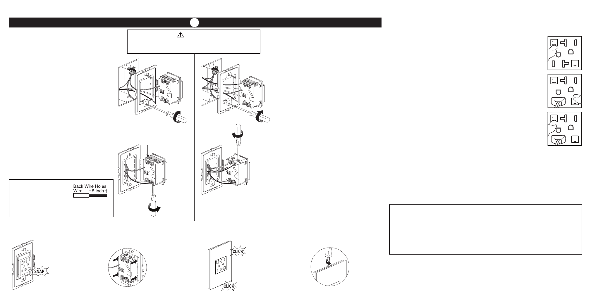
7. Connect the wires (choose A or B). . .only after reading other side completely
A: One cable (2 or 3 wires) entering the box
B: Two cables (4 or 6 wires) entering the box
or
About wire connections.
If necessary,cut wires and strip
insulation using stripping guide
on back of outlet.
1. Insert wire to bottom of hole.
2. Securely tighten screw beneath
wire hole to retain inserted wire.
WARNING
Failure to connect the ground wire will result in an
unsafe installation that could lead to personal injury.
Yellow sticker remains
in place to cover the
LOAD terminal screws.
reset
test
Carefully fold the wires
into box, keeping the
grounding wire away
from the White and Hot
terminals.
Snap outlet into frame.
8. Snap outlet into frame
NOTE – If you need to remove outlet
after snapping into frame, first remove
frame from wall box to access the four
locking tabs on the back
of the outlet. Insert a flat
screwdriver to depress
tabs as you apply pres-
sure to push outlet out.
9. Snap wall plate to frame
Snap wall plate to frame.
There are three click-
stops to adjust the fit of
the wall plate to the out-
let and the wall.
NOTE – To remove wall plate,
insert a small, flat screwdriver in
notches on wall plate and twist
gently to pry
from frame.
Ratings:
15A 125V 60Hz
20A 125V 60Hz
Technical Assistance:
(877) 295-3472
www.adornemyhome.com/install