Is-0429 rev. o – Legrand HA5201-WH User Manual
Page 2
INSTRUCTION / INSTALLATION SHEET
TV Display Interface
IS-0429 Rev. O
301 Fulling Mill Road, Suite G
Middletown, PA 17057
Phone (800) 321-2343 / Fax (717) 702-2546
www.onqlegrand.com
©Copyright 2008 by On-Q/Legrand All Rights Reserved.
Page 2 of 2
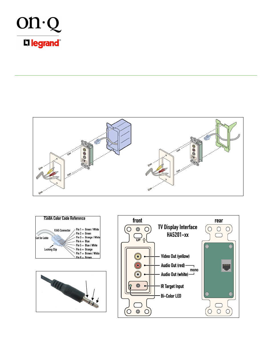
Figure 3
Figure 4
Figure 6
Figure 5
4. INSTALLATION
As shown in Figure 3 a single Cat 5 cable is run during “rough-in” from the enclosure to the intended location of each TV Display
Interface. The Cat 5 is terminated with an RJ45 plug following the T568A specification (see Figure 4).The Cat 5 cable is then
plugged into the rear of the TV Display Interface and it may then be mounted (during “trim-out”) in a low voltage bracket or electrical
box. RCA cables are used for connection to the Homeowner’s TV. The AC1016 Universal IR Target is plugged into the bottom jack
on the front of the TV Display Interface (see Figure 5 for pinout). The LED next to the connector (see Figure 6) is normally green to
indicate power is available to the TV Display Interface and blinks red when there is IR activity.
Ground
IR signal
+12VDC