Instruction/installation sheet network centers, Is-0141 rev. b – Legrand 364397-01 User Manual
Page 2
301 Fulling Mill Road, Suite G
Middletown, PA 17057
Phone (800) 321-2343 / Fax (717) 702-2546
www.onqlegrand.com
Page 2 of 2
INSTRUCTION/INSTALLATION SHEET
Network Centers
IS-0141 REV. B
©Copyright 2008 by On-Q/Legrand All Rights
Reserved
.
6)
Cables at rough-in should be cut at the bottom of the network center.
7)
Secure all cables in a manner to protect them during drywall and trim out. Cables must remain
accessible to be easily retrieved after drywall.
8)
Run a ground wire from the network center location to the house ground.
C.
Network Center Physical Installation
1)
The network center must be mounted securely. For recessed wired installations, locate the stud
holding the low voltage bracket or junction box. Install a drywall or wood screw one (1) inch
above the top of the opening, leaving the head slightly raised. Using the keyhole on the network
center, hang the network center. Level the network center and temporarily install a screw in the
lower hole. Mark the locations for the other two (2) holes. Remove the network center and install
anchors for the two (2) screws not on the stud. Re-install the network center. Tighten securely.
2)
Pull the cables through rectangular opening at the top of the network center. Cable for other
applications on the Advanced Network Center can be fed behind and through the large opening
below the integral telephone distribution panel.
3)
Terminate and connect video cables. Locate video source cable (CATV or antenna), position to attach to
the input of the splitter. Cut the cable approximately two (2) inches beyond the splitter, allowing slack for
cable management. Use a high quality cable cutter to avoid distortion of the cable and center conductor. If
cable marking is cut off, re-mark in an area that will be visible after installation. Strip and prep cable per
connector instructions. Use a coax cable stripper to ensure clean cuts without damaging the center
conductor. Install high quality “F” style connectors. Use proper insertion and crimp tools. Attach securely to
the proper port of the splitter. Repeat for outlet cables.
4)
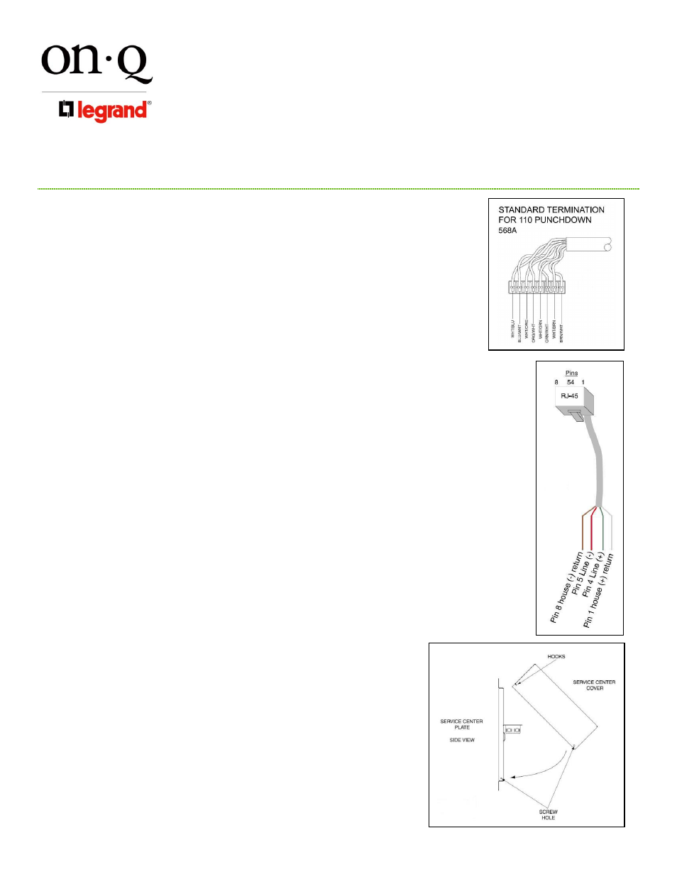
Connect Telephone Service. Identify incoming service cable and route to “Line In” 110 punch-down block.
Route cable allowing some slack for cable management and trim cable about two (2) inches beyond the
connector. If cable marking is removed, re-mark cable in the area that will be visible after installation. Strip
off approximately three (3) inches of the other jacket using On-Q strip tool (P/N 363292-01) or equivalent.
Position pairs over color-coded slots on the connector (see Figure 2).
NOTE: Do not untwist pairs
NOTE: White wires may not have color trace stripe. Keep white wire paired with appropriate colored
wire.
Without un-twisting cable, position the wires in the individual slots. Punch down and trim wires using On-Q
Punch down Tool (P/N 363293-01) or equivalent. Remove excess wire and tug slightly on cable to ensure
wire is securely installed in connector. Repeat for outlet cables.
5)
After all cables are connected, cables should be grouped and bundled for ease of maintenance.
6)
Connect ground wire to ground lug and to ground in outlet. Follow NEC and local codes in installing
ground wire.
D.
Testing and Troubleshooting
1)
All cables should be checked to ensure pairs are maintained on category cable and that there
are no opens or shorts on any of the circuits. The Coax/UTP tester (P/N 364276-01) makes this
test quick and easy.
2)
Locating faults can be accomplished using tone generator and probe.
3)
After service is activated, be certain network is working at all outlets.
E.
Other Advanced Network Center Applications
1)
The security interface can be enabled to allow line seizure and dial out capability
to most security systems. Connect the RJ31X cable (supplied w/security system)
to the RJ45 “security” jack. Turn off “Line 1” on the test switch to activate the
security line. Connect the terminals of the RJ31X cable as described in security
system instructions (see Figure 3).
2)
Surge protection for the telephone may be enhanced using the On-Q Surge
Suppressor Unit (P/N 363487-01). See instructions with unit for installation.
F.
Cover Installation (optional) see Figure 4
1)
Hang cover on the top of the network center using integral hooks. Swing the
bottom in place. Use care to ensure cables do not become pinched.
2)
Secure and electrically ground the cover to the network center using screws and
star washers provided.
Figure 2
Figure 3
Figure 4