Is-0011 rev. g – Legrand 363484-01 User Manual
Page 2
301 Fulling Mill Road, Suite G
Middletown, PA 17057
Phone (800) 321-2343 / Fax (717) 702-2546
www.onqlegrand.com
Page 2 of 2
INSTRUCTION/INSTALLATION SHEET
1x11 Telecom Modules
IS-0011 REV. G
©Copyright 2008 by On-Q/Legrand All Rights
Reserved
.
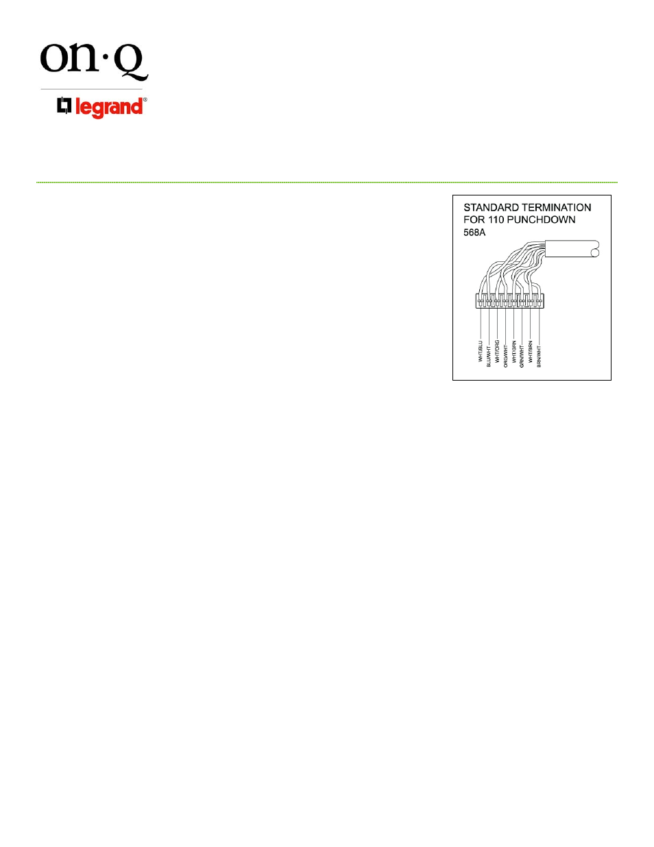
2) Strip off 4” of outer jacket and position pairs over color-coded slots of
connector (see Figure 3).
NOTE: Do not untwist pairs.
NOTE: White wires may npt have color trace stripe. Keep white wire
paired with appropriate colored wire based on twist.
3) Without untwisting cable, position the wires in the individual slots and
punch down and trim each wire (see Figure 3).
4) Remove any excess wire and tug lightly on the cable to insure a
secure punch down connection.
C. Outlet Cable Termination (see Figure 3)
1) Route outlet Cat 5e cables to numbered 110-style punch down
blocks, allowing slack for bundling, and cut each cable about 2” past
the associated connector.
2) Strip off 4” of outer jacket and position pairs over color-coded slots of
connector (see Figure 3).
NOTE: Do not untwist pairs.
NOTE: White wires may npt have color trace stripe. Keep white wire paired with appropriate
colored wire based on twist.
3) Without untwisting cable, position the wires in the individual slots and punch down and trim each wire
(see Figure 3).
4) Remove any excess wire and tug lightly on the cable to insure a secure punch down connection.
5) Record room name/number on wire layout label inside the enclosure.
D. Wide Area Network Cable Termination (see Figure 3)
1) Route incoming/outgoing WAN Cat 5e cable to “In/Out” 110-style punch down block in WAN area,
allowing slack for bundling, and cut the cable about 2” past the associated connector.
2) Strip off 4” of outer jacket and position pairs over color-coded slots of connector (see Figure 3).
NOTE: Do not untwist pairs.
NOTE: White wires may npt have color trace stripe. Keep white wire paired with appropriate
colored wire based on twist.
3) Without untwisting cable, position the wires in the individual slots and punch down and trim each wire
(see Figure 3).
4) Remove any excess wire and tug lightly on the cable to insure a secure punch down connection.
5) Complete the WAN Cable Termination by installing a Cat 5e jumper between the RJ-45 “In” jack and
“Out” jack.
E. Other Applications
1) RJ-31x Security Interface - Connect RJ-31x cable from security system to “Security” jack and place switch
#1 into the “off” position.
2) Surge Protection – For more details see instructions supplied with 363487-01.
3) PBX/KSU Wiring – For more details see instructions supplied with PBX/KSU Interface Kit (IS-0015).
Figure 3