Is-0162 rev. a – Legrand 364400-xx User Manual
Page 2
301 Fulling Mill Road, Suite G
Middletown, PA 17057
Phone (800) 321-2343 / Fax (717) 702-2546
www.onqlegrand.com
Page 2 of 2
©Copyright 2008 by On-Q/Legrand All Rights Reserved.
INSTRUCTION/INSTALLATION SHEET
Combo Modules (B Series)
IS-0162 REV. A
2) Attach an RG-6 “F” connector to each cable and connect to a fitting
on the module and finger tighten.
NOTE: Do not bend cable in less than a 2 inch radius.
NOTE: Cables should all be labeled. Record room locations for cables
to the outlets.
D. Incoming Telecom Service Cable Installation (see Figure 4):
1) Route incoming service cable to “Line In” 110 punch down strip on
module. Allow slack for bundling and trim cable 2 inches beyond
punch down strip.
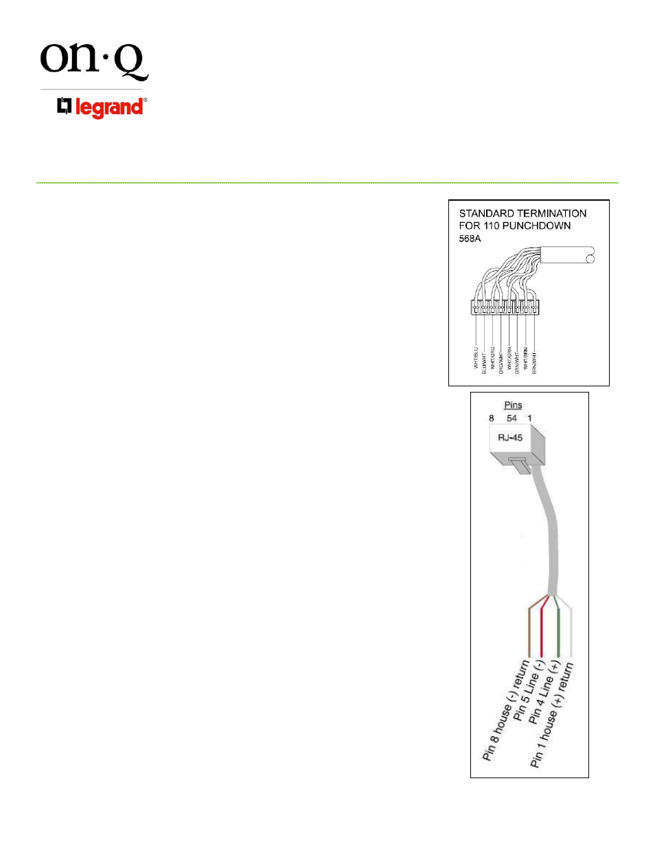
2) Strip off approximately 4 inches of the outer jacket and position the
pairs over the color coded slots on the 110 strip (see Figure 4).
NOTE: Do not untwist pairs. White wires may not have color trace
stripe. Keep white wire paired with appropriate colored wire.
3) Punch down and trim wires using a punch down tool and remove any
excess wire.
4) Tug lightly on the cable to insure wire is securely fastened.
E. Outlet Telecom Cable Termination:
1) Route outlet telecom cables to appropriate numbered 110 punch
down strips on module. Allow slack for bundling and trim cables 2
inches beyond punch down strip.
2) Strip off approximately 4 inches of the outer jacket and position the
pairs over the color coded slots on the 110 strip (see Figure 4).
NOTE: Do not untwist pairs. White wires may not have color trace
stripe. Keep white wire paired with appropriate colored wire.
3) Punch down and trim wires using a punch down tool and remove any
excess wire.
4) Tug lightly on the cable to insure wire is securely fastened.
5) Record room names/numbers and connection numbers on wire
layout label inside enclosure.
F. Securing Cables:
1) After all cables are connected to the module, the cables should be
bundled with wire management straps and grouped to allow ease of
maintenance.
4. Other Applications (If Applicable)
A. Security Interface (see Figure 5):
1) To enable line seizure and dial out capability to most security
systems, connect the RJ-31X cable (supplied with the security
system) to the RJ-45 “Security” jack on the module. TURN OFF Line
1 to activate the security link. Connect the other end to the security
system as outlined in the security system installation instructions.
2) To disable security, remove the connector from the “Security” jack
and set Line 1 to “ON”.
Figure 4
Figure 5