Installation and operating instructions – Louroe Electronics LE-575 User Manual
Page 2
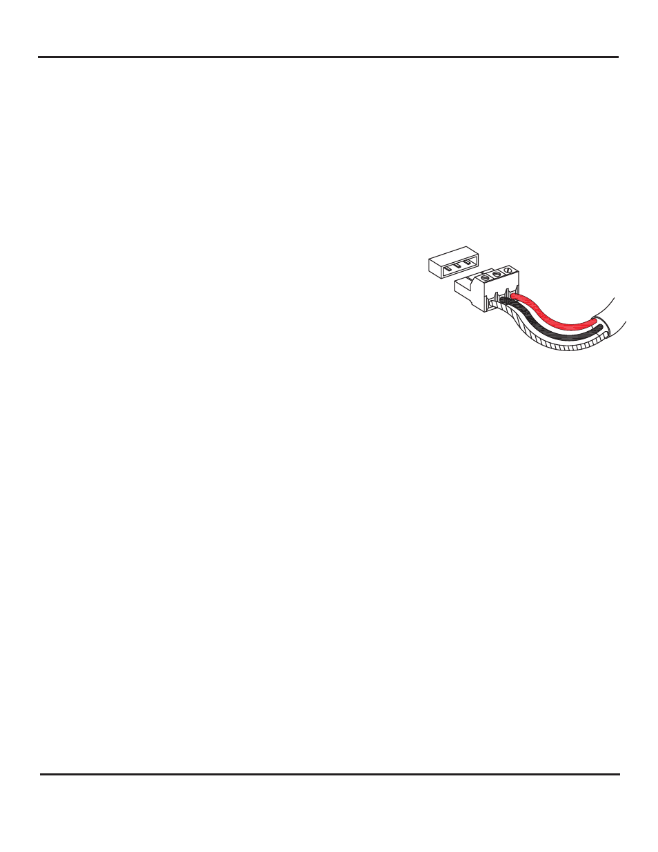
MICROPHONE CONNECTION
If using West Penn 452 or equivalent with same color code, starting from
right to left of the pluggable connector, connect as follows: (See
connections on right)
1. Red wire (12 Vdc) connects to terminal A or right hand most
terminal of the pluggable connector.
2. Black wire (audio out) connects to terminal B or middle terminal
of the pluggable connector
3. Bare wire (ground) connects to terminal C or left hand most of
the pluggable connector.
4. After all 3 wires are tightened in place on the pluggable
connector, plug it in to the 3 pin header located on the
pcboard. See interconnection diagram on next page.
INSTALLATION TIP: If area to be monitored for audio is noisy or has background disturbances, the
microphone should be positioned close to the subject (4’ - 8’) if possible. Also, the microphone output can be
lowered by adjusting the gain control potentiometer. Rotating clockwise will increase the gain;
counterclockwise decreases the gain. The factory setting is 0dB output.
A represents +12 Vdc Power
B represents Audio Output
C represents Ground
A 3-pin header is located on the back of the microphone housing, marked A, B, C.
CONNECTING VERIFACT EGC MICROPHONE TO A LOUROE BASE STATION OR AUDIO
INTERFACE ADAPTER
CONNECTING VERIFACT™ E-AGC MICROPHONE TO OTHER AUDIO DEVICES.
If a Louroe audio base station is not used and microphone is being connected directly to another receiver from
other manufacturers, 12 Vdc power must be applied to terminals A and C. (A is positive, C is negative).
Terminals B and C of microphone (C is common) go to the “Audio In” or “Line in” of the audio source. We
recommend shielded cable connections for terminal B and C (See last page for interconnection diagram)
All Louroe audio base stations and Interface Adapters have corresponding terminal blocks marked A, B, C.
Connect other end of cable as follows:
1. Red wire from microphone connects to pin A of Base Station (12Vdc)
2. Black wire from microphone connects to pin B of Base Station (Audio Output)
3. Bare wire from microphone connects to pin C of Base Station (Ground)
INSTALLATION AND OPERATING INSTRUCTIONS
Page 2 of 4
LOUROE ELECTRONICS 6 9 5 5 VA L J E A N AVENUE, VAN NUYS, CA 91406
TEL (818) 994-6498
FAX
994-6458
website: www.louroe.com e-mail: [email protected]
(818)
®
Verifact EGC microphone Is designed for surface mounting to a wall or a pole. It should be located 6 to 8 ft. from
the area of desired coverage. One inch threaded knock-outs are located at the top and back side of the Bell Box
for conduit connection. As a finished unit, the Verifact E-AGC microphone is classified as Weather Resistant .
Sealing around faceplate and conduit connection is required. Make certain that when Verifact EGC assembly is
mounted, the microphone portion is facing downwards.
MECHANICAL INSTALLATION
Egc_mic-inst_12/14
®
®
®
®