Installation and operating instructions, Illustrated parts, Fig. 2 – Louroe Electronics ASK-4 350 User Manual
Page 2
Page 2 of 8
LOUROE ELECTRONICS® 6 9 5 5 VA L J E A N AVENUE, VAN NUYS, CA 91406
TEL (818) 994-6498
FAX
994-6458
website: www.louroe.com e-mail: [email protected]
(818)
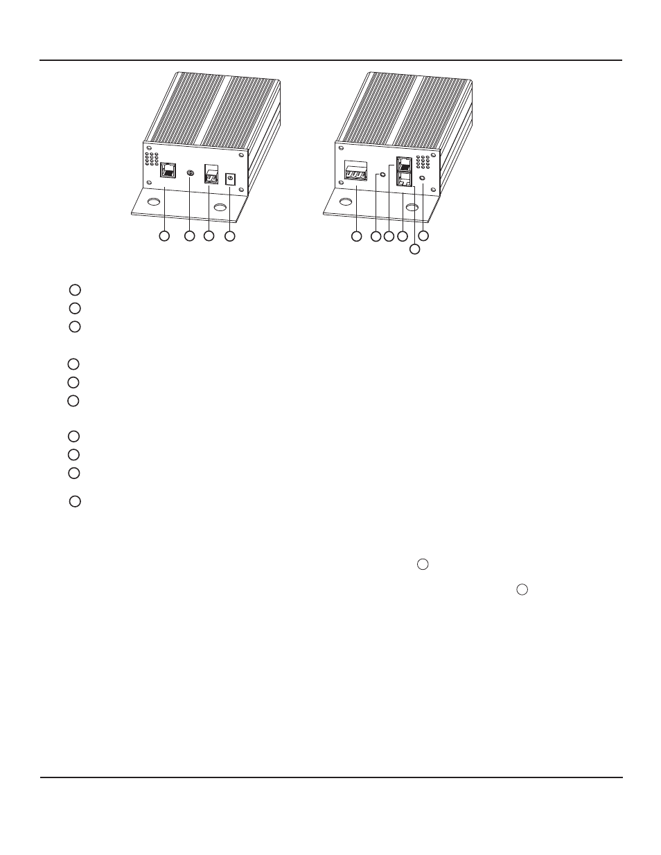
ILLUSTRATED PARTS
1
2
3
4
5
6
7
8
9
10
Power+Data Output Jack
MIC Out Adjust
DC Out Terminal Block
DC IN Power Jack
Mic/Speaker Audio Terminal Block
Audio Input Jack
Data Out Only Jack
Power+Data Input Jack
Audio Output Jack
Power Indicator
Connects to PoE IP Cameras and/or Encoder
Adjust the audio output gain of the microphone
Receives 12Vdc power from external power supply (not supplied)
Receives wiring from Louroe Verifact Microphone and/or AOP-SP series
Connects to data input of Non-PoE IP Cameras, and Encoders.
Connects to PoE (802.3af) Switch or PoE (802.3af) Midspan
Lights Green indicating power is present to the unit
Connects to audio input of IP cameras,
Encoder, etc.
Provides audio to IP Cameras, Encoder, etc.
Receives audio from IP Camera, Encoder, etc. and connects to audio
output for talkback operation
Provides +12Vdc voltage to power external equipment such as
Non-PoE cameras, encoders, relays, etc.
FIG. 2
POE INTERFACE/POWER EXTRACT
OR
POWER + DATA
OUT
IEEE 802.3af
POE
MIC OUT
ADJUST
DC OUT
GND + 12V
DC IN
+12V
AUDIO
DATA OUT
P/N:LE-520
MIC/SPEAKER
OUT
IN
AUDIO
A B C SP
POWER + DA
TA
IN
1
2
3
4
5
6
7
8
9
10
REAR PANEL
FRONT PANEL
INSTALLATION AND OPERATING INSTRUCTIONS
1. Do not connect non-PoE complaint devices to Power+Data Output Jack . Failure to do so may damage the
powered equipment.
Plan ahead where to install before making any connections.The IF-PX is designed to operate within 6’ of the camera so
the audio cables supplied can be connected between the IF-PX and camera. The maximum distance between the IP
camera and PSE is 100m or 328’.
2. Do not connect wiring from external microphone to the Mic/Speaker Audio Terminal Block until all the
ethernet cables (RJ45) are connected and power is present to the camera. Failure to do so in sequence, the
camera may not receive power.
CAUTION
NOTES
5
1
FIG. 2
Ask4_350_inst 2/15