Installation and operating instructions, Illustrated parts, Fig. 2 – Louroe Electronics ASK-4 370 User Manual
Page 3
CONNECTING PoE SWITCH TO PoE IP CAMERA OR ENCODER (See Fig. 3 and 4)
1. Connect Ethernet cable from PSE (Power Source Equipment) to the Power+Data Input Jack of the IF-PX.
2. Connect Ethernet cable from camera to Power+Data Output Jack of the IF-PX. Camera should now have power
and data running through it. Power Indicator lights up.
4. AOP-SP Connection (two-way audio): Before connecting the AOP-SP series, make sure that the Ethernet
cables between the PSE, IF-PX and Camera are all connected.
a) Connect a 3 cond shielded cable between the AOP-SP and the pluggable header (Mic/Speaker Audio Terminal
Block) of the IF-PX. Connect terminal A of the AOP-SP to terminal A of IF-PX; connect terminal B of AOP-SP to
terminal B of IF-PX; terminal C of AOP-SP to terminal C of IF-PX and terminal SP of AOP-SP to terminal SP of IF-
PX.
b) Using the patch cable (stereo plug to stereo plug), connect the Audio Output Jack of the IF-PX to the audio input
of the camera or encoder. Connect the Audio Input Jack of IF-PX to audio output of the camera or encoder. See
interconnection diagram on page 5.
c) See installation instructions of AOP-SP for setting up and operation of the unit.
5. Setup camera for video and audio monitoring. Use an amplified speaker and a microphone to test the audio. A push
to talk microphone is recommended to minimize the echo when doing two-way audio. See camera user manual for
setting up the camera to the network.
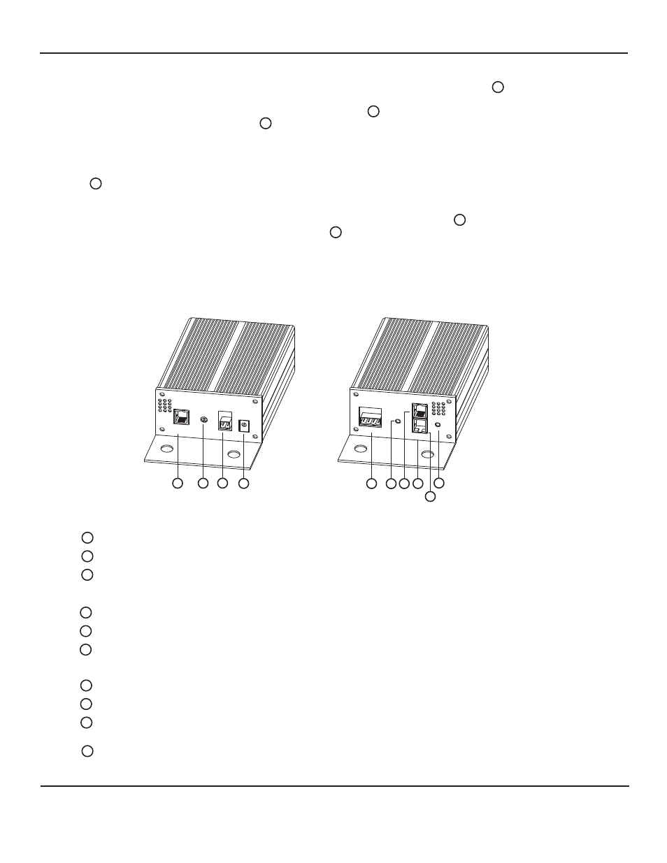
ILLUSTRATED PARTS
1
1
2
3
4
5
5
6
6
7
8
8
9
9
10
10
Power+Data Output Jack
MIC Out Adjust
DC Out Terminal Block
DC IN Power Jack
Mic/Speaker Audio Terminal Block
Audio Input Jack
Data Out Only Jack
Power+Data Input Jack
Audio Output Jack
Power Indicator
Connects to PoE IP Cameras and/or Encoder
Adjust the audio output gain of the microphone
Receives 12Vdc power from external power supply (not supplied)
Receives wiring from Louroe Verifact Microphone and/or AOP-SP series
Connects to data input of Non-PoE IP Cameras, and Encoders.
Connects to PoE (802.3af) Switch or PoE (802.3af) Midspan
Lights Green indicating power is present to the unit
Connects to audio input of IP cameras,
Encoder, etc.
Provides audio to IP Cameras, Encoder, etc.
Receives audio from IP Camera, Encoder, etc. and connects to audio
output for talkback operation
Provides +12Vdc voltage to power external equipment such as
Non-PoE cameras, encoders, relays, etc.
FIG. 2
POE INTERFACE/POWER EXTRACT
OR
POWER + DATA
OUT
IEEE 802.3af
POE
MIC OUT
ADJUST
DC OUT
GND + 12V
DC IN
+12V
AUDIO
DATA OUT
P/N:LE-520
MIC/SPEAKER
OUT
IN
AUDIO
A B C SP
POWER + DA
TA
IN
1
2
3
4
5
6
7
8
9
10
REAR PANEL
FRONT PANEL
Page 3 of 4
LOUROE ELECTRONICS 6 9 5 5 VA L J E A N AVENUE, VAN NUYS, CA 91406
TEL (818) 994-6498
FAX
994-6458
website: www.louroe.com e-mail: [email protected]
(818)
®
INSTALLATION AND OPERATING INSTRUCTIONS
Ask4_370_inst_2/15