Installation and operating instructions – Louroe Electronics TLO User Manual
Page 2
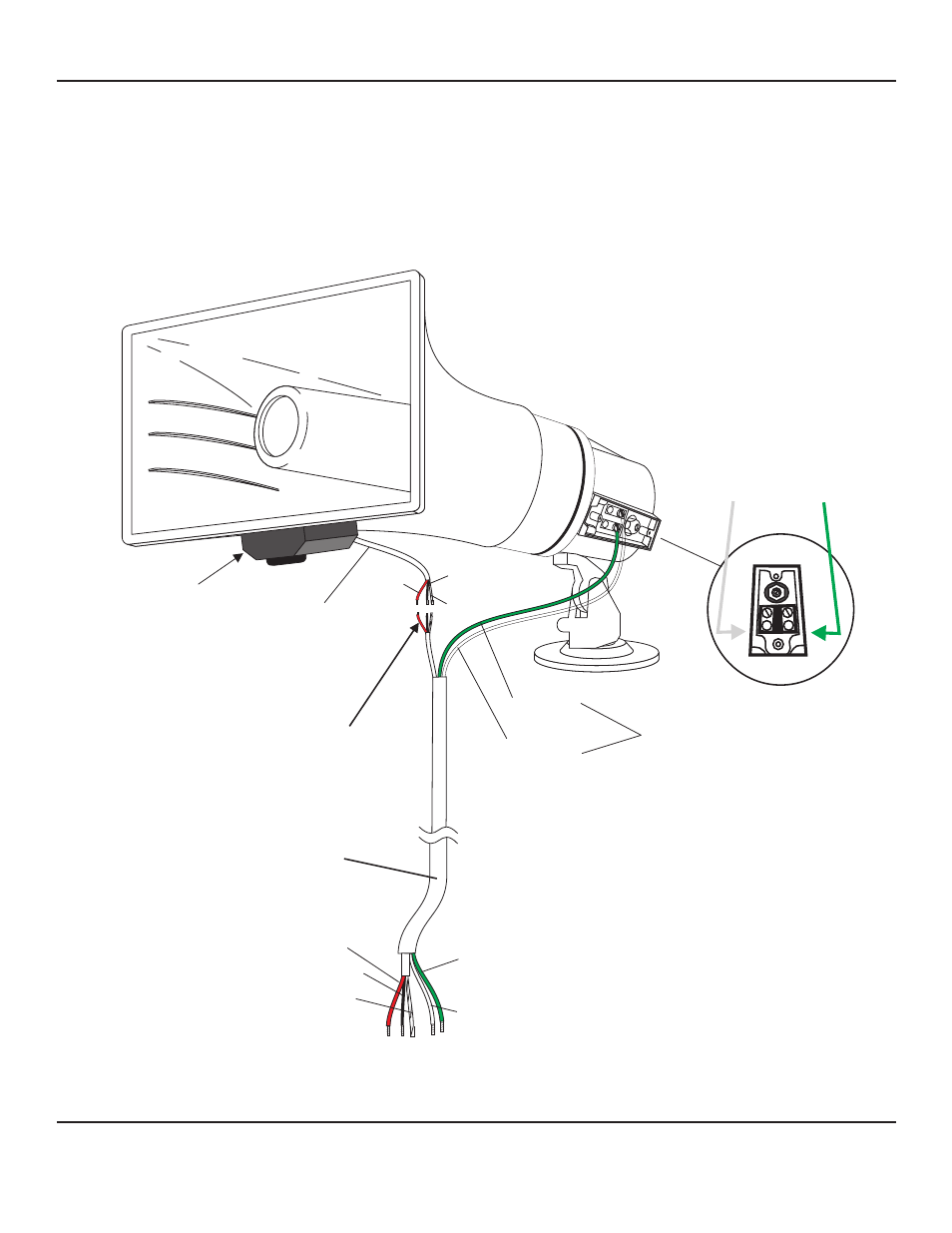
CONNECTING TLO TO A LOUROE BASE STATION
POSITIONING TLO
Model TLO is compatible with all Louroe™ audio base stations that feature two-way talk/listen communication. All
Louroe™ base stations contain terminal blocks for receiving both microphone and speaker connections from Model
TLO. For wiring and installation instructions, please refer to the specific Louroe™ Base Station being used.
After TLO has been mounted to desired structure (wall, pole, etc.), horn should be tilted in a downward position.
This will protect the microphone element from water damage.
1
2
1
2
3
5
6
7
Speaker terminal screws
green wire to #2 (positive +)
white wire to #1 (ground -)
to Louroe base station
Refer to the specific base station instructions for connections
(C) BARE
(A) RED
(B) BLACK
MICROPHONE
CONNECTION
Connects to
Terminals A, B, C
of Louroe Base
Station
{
Green = speaker (positive)
connects to terminal “SP” of base station
White = speaker (negative)
connects to terminal “G” of base station
MICROPHONE
CABLE
MICROPHONE
HOUSING
WHITE
(GROUND)
Microphone connection
using three wire nuts
Red = 12Vdc
Black = Audio Output
Bare = Ground
RED
SPEAKER
BLACK
BARE
GROUND (-) POSITIVE (+)
GREEN
(POSITIVE)
Page 2 of 4
LOUROE ELECTRONICS™ 6 9 5 5 VA L J E A N AVENUE, VAN NUYS, CA 91406
TEL (818) 994-6498
FAX
994-6458
website: www.louroe.com e-mail: [email protected]
(818)
INSTALLATION AND OPERATING INSTRUCTIONS
tlo inst 3/15