Rear of tlsp-cm, Installation and operating instructions – Louroe Electronics TLSP-CM User Manual
Page 3
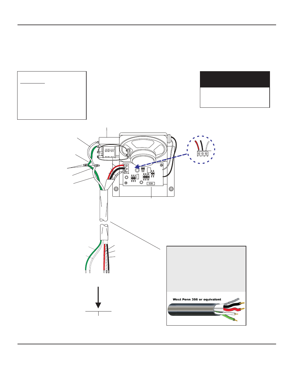
Terminal Block Identification
Microphone
C - Ground
B - Audio Output
A - 12Vdc Power
Green wire (positive)
White wire (negative)
are speaker connections
WIRING DIAGRAM FOR
MODEL TLSP-CM (CORNER MOUNT)
SPEAKER/MICROPHONE
70V
TRANSFORMER
MICROPHONE SENSITIVITY SWITCH
USED ONLY FOR LOWERING THE GAIN - 6dB
TO REDUCE BACKGROUND AND PICKUP
RED
BLACK
BARE
REAR OF TLSP-CM
A
A
B
B
C
C
GREEN
WHITE
WIRE NUT
NOTE: IF USING CABLE
FROM OTHER
MANUFACTURERS,
COLOR CODE MAY VARY
RED (A)
BARE (C)
BLACK (B)
Refer to installation instructions
on page 1 or to the specific
Louroe Base Station
A B C
GREEN (+)
WHITE (-)
UNSHIELDED
SPEAKER
AND ALARM
CONNECTION
SHIELDED
MICROPHONE
CONNECTION
POSITIVE NEGATIVE
}
}
MICROPHONE
CONNECTION
SPEAKER
WHITE
(-)
SPEAKER
GREEN
(+)
MICROPHONE TERMINAL
BLOCK IDENTIFIER
A = 12Vdc Power (red)
B = Audio Outputs (black)
C = Ground (bare)
WIRING REQUIREMENTS
4 Conductor consisting of:
+
2 Conductor shielded, 20 gauge
with 22 gauge drain (microphone
connection)
+
2 Conductor unshielded, 18 gauge
(speaker connection)
All in the same jacket
West Penn 356 or equivalent
A B C
Page 3 of 4
LOUROE ELECTRONICS 6 9 5 5 VA L J E A N AVENUE, VAN NUYS, CA 91406
TEL (818) 994-6498
FAX
994-6458
website: www.louroe.com e-mail: [email protected]
(818)
®
tlsp_cm_inst_3/15
INSTALLATION AND OPERATING INSTRUCTIONS