Interconnection diagram, Installation and operating instructions, Wiring requirements – Louroe Electronics IF-1 User Manual
Page 3: Rca connector cable used with this application
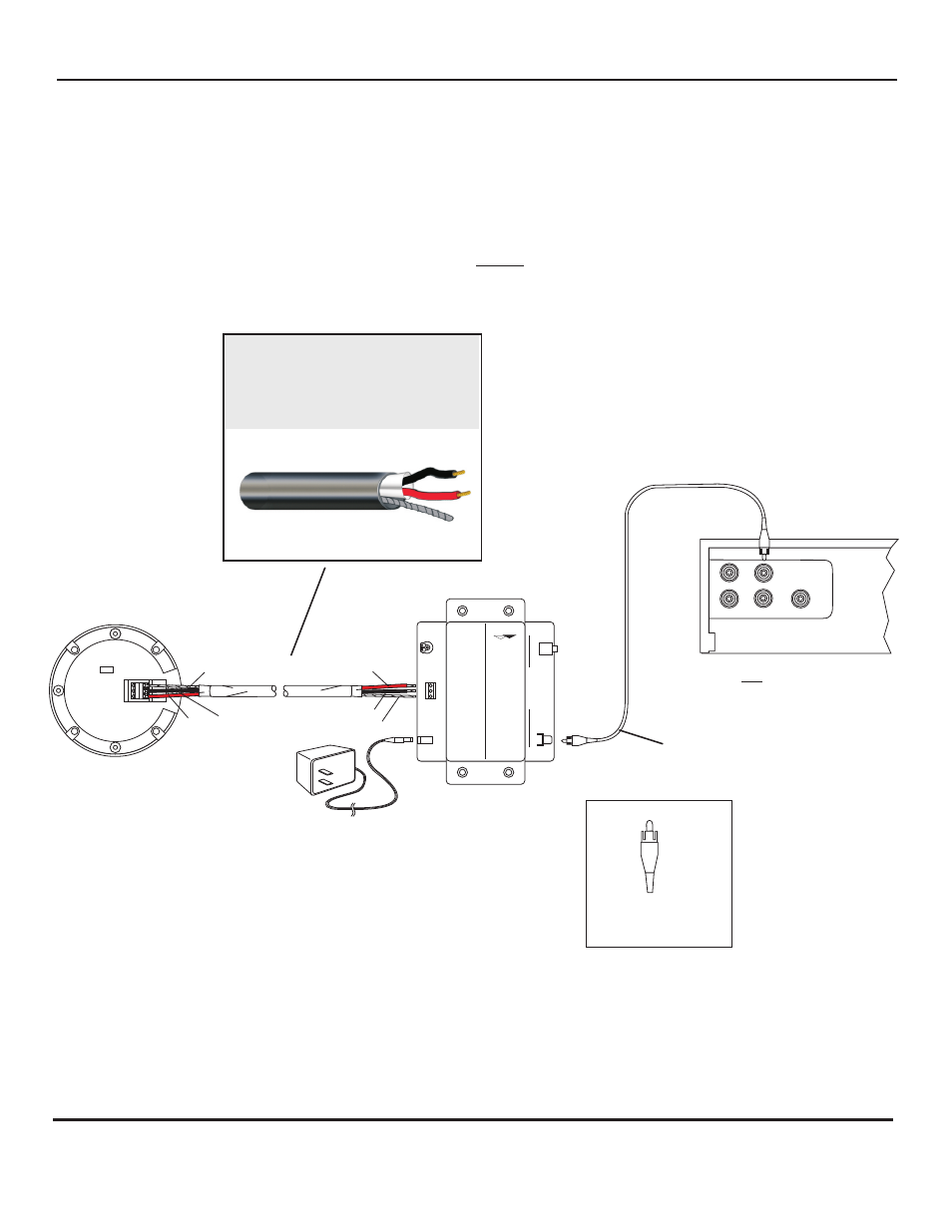
INTERCONNECTION DIAGRAM
BETWEEN
A LOUROE MICROPHONE
AND IF-1 INTERFACE ADAPTER
FOR CONNECTION TO A DVR/VCR, ETC.
WITH RCA INPUT
L
N
A
BARE
A
B
C
V
E
R
IF
A
C
T A
L
N
BLACK
RED
VERIFACT A MICROPHONE SHOWN
All Louroe microphones
are compatible with the IF-1
BLACK
RED
BARE
MODEL IF-1
RCA CONNECTOR CABLE
AD-1
+12 Vdc
POWER
SUPPLY
MIC INPUT
A
B
C
RCA
IF
-1
IN
TE
R
FA
C
E A
D
A
P
TE
R
E
L
O
U
R
O
E
L
E
C
T
R
O
N
I
C
S
AUDIO OUT
CONTROL
3.5mm MONO
3.5mm STEREO
AUDIO OUTPUTS
+12 Vdc
RCA
OUTPUT
AUDIO OUT
AUDIO IN
REAR PANEL OF DVR WITH
RCA TYPE AUDIO INPUT
RCA PLUG
RCA connector cable
used with this
application
2 Conductor shielded cable, 22
gauge with a 24 gauge drain wire
NOTE:
Unshielded cable is not
satisfactory for audio systems
WIRING REQUIREMENTS
West Penn 452 or equivalent
INSTALLATION AND OPERATING INSTRUCTIONS
Page 3 of 8
LOUROE ELECTRONICS 6 9 5 5 VA L J E A N AVENUE, VAN NUYS, CA 91406
TEL (818) 994-6498
FAX
994-6458
website: www.louroe.com e-mail: [email protected]
(818)
®
IF_1_inst_5/15
®