Interconnection diagram, Installation and operating instructions, Lectronic s – Louroe Electronics IF-2 User Manual
Page 3
1
2
3
4
VIDEO SERVER
audio input
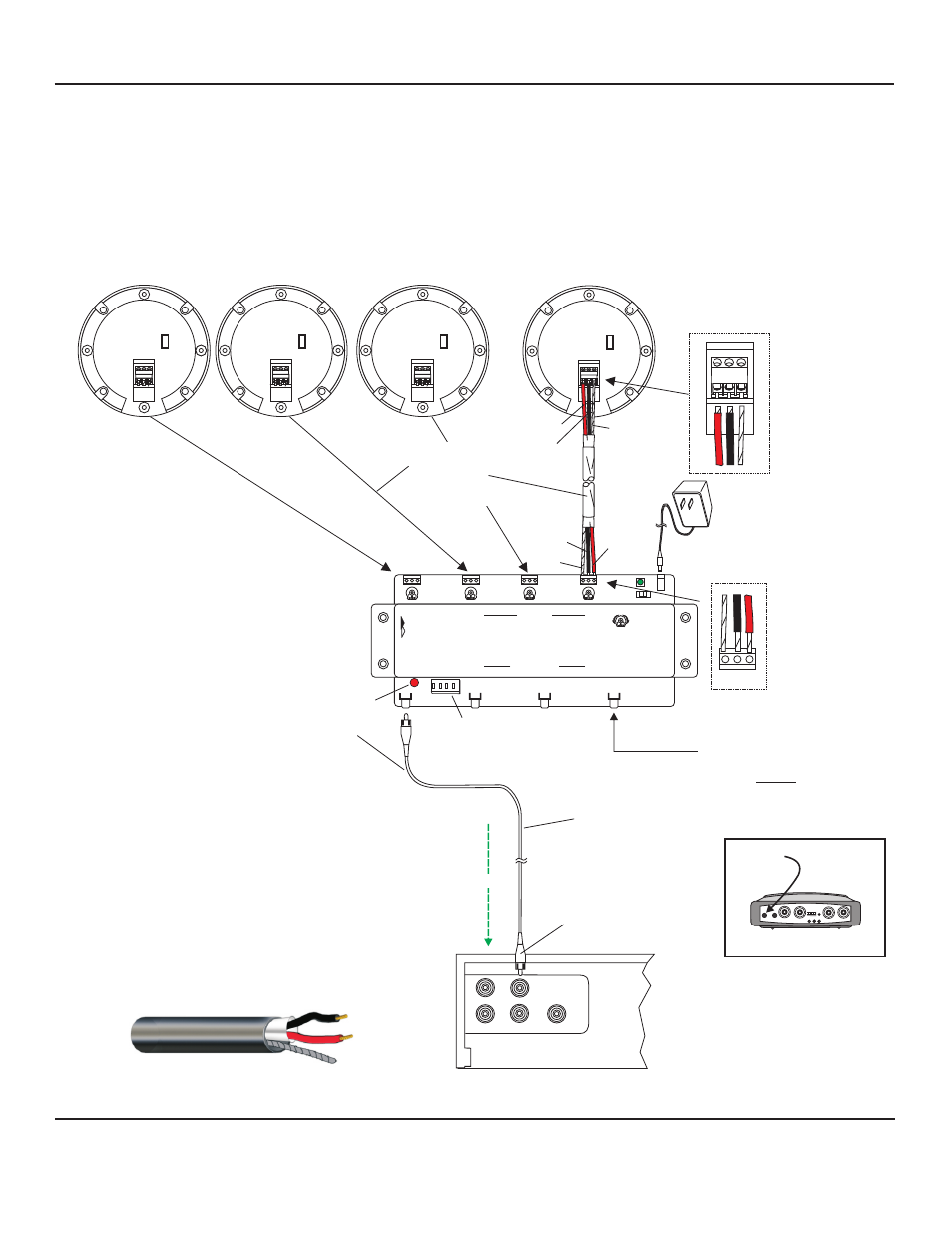
INTERCONNECTION DIAGRAM
FOR
CONNECTING LOUROE VERIFACT MICROPHONES
TO A DVR WITH MULTIPLE AUDIO INPUTS USING
LOUROE MODEL IF-2, IF-4 OR IF-8 AUDIO INTERFACE ADAPTER
(IF-4 used as an example)
1
1
1
1
+12 Vdc POWER
SUPPLY (INCLUDED)
1
E
L
OUROE
LECTRONIC S
IF-4
FOUR ZONE AUDIO INTERFACE ADAPTER
AUDIO OUTPUTS
MIC INPUTS
AUDIO LEVEL CONTROL
BLACK
BARE
RCA output
Use 3.5mm mono to RCA
cable of IF-4 for
connection to
Video Server or IP camera
Audio Out
Audio Indicator Light
Audio Test Switch
Audio In
BARE
A B C
V E R I FA C T A
L
N
A B C
V E R I FA C T A
L
N
BLACK
RED
All Louroe microphones
VERIFACT A, B, C, D, D-V, E, K, L-DT
are compatible with Louroe IF-2,
IF-4 and IF-8 Audio Interface Adapters
Verifact A Microphone shown as an example
with IF-4 Interface Adapter
IF-2 will accommodate
2 Louroe™ microphones
IF-4 will accommodate up to
4 Louroe™ microphones
IF-8 will accommodate up to
8 Louroe™ microphones
Back side of
Verifact™ A Microphone Shown
2
3
4
LOUROE MODEL IF-4
AUDIO INTERFACE ADAPTER
(Connections for IF-2 and IF-8 are same as above)
AUDIO OUT
AUDIO IN
RCA CABLE CONNECTS FROM
“AUDIO OUT” OF IF-4 TO
“AUDIO IN” OF DVR, ETC.
DVR WITH RCA TYPE AUDIO INPUTS
A
A
B
B
C
C
A B C
V E R I FA C T A
L
N
A B C
V E R I FA C T A
L
N
2 CONDUCTOR
SHIELDED
22 GAUGE
WEST PENN
452 OR EQUIV.
Red - 12Vdc power
Black - Audio Output
Bare - Ground
ON
RS
1
2
3
4
R
RED
West Penn 452
or equivalent
Audio Path
INSTALLATION AND OPERATING INSTRUCTIONS
Page 3 of 4
LOUROE ELECTRONICS 6 9 5 5 VA L J E A N AVENUE, VAN NUYS, CA 91406
TEL (818) 994-6498
FAX
994-6458
website: www.louroe.com e-mail: [email protected]
(818)
®
If_248_inst_3/15
®
®
®