Lynx Studio LT-FW User Manual
Page 23
Page 23 of 43
the monitor source for Analog Out 1 while holding down the CTRL key, LSLOT In
1-16 will be assigned to Analog Out 1-16).
y
These faders allow control over the output level of each monitor source when in
Remote Routing mode. This level attenuation occurs in the digital domain, so it is
recommended to leave these faders in their default, maximum position in situations
where the highest fidelity is required. Holding down the SHIFT key on the keyboard
while adjusting a fader, will cause adjustment of channel pairs.
u
This display reveals the amount of attenuation, in dB, of a monitor source.
i
This button enables the mute function for the associated monitor source.
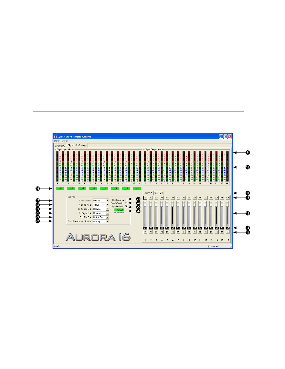
7.3.2 Digital I/O & Settings Page
This page is viewable by clicking the “Digital I/O & Settings” Tab in the top left corner of
the Aurora Remote Control application.
o
These indicators will illuminate when three consecutive full-scale samples are
detected on the Aurora Digital Inputs and Outputs or when a summing overrun occurs
on the Aurora Digital Outputs. The indicator will remain illuminated for 250ms.
a
These meters display the instantaneous peak level of audio being sent to the Aurora
Digital Inputs and Outputs.
s
These tabs allow monitor source groups to be selected for the Digital Outputs when
Remote Routing is utilized. The Aurora can be set for global routing (i.e. AES In
routes to Analog Out) or Remote Routing. With Remote Routing up to two sources
(Source A and Source B) can be established for each output. For these sources to be
active, the TO DIGITAL OUT switch on the Digital I/O & Settings page must be set