10 analog input range register – Measurement Computing CIO-DAS16/330 User Manual
Page 17
Advertising
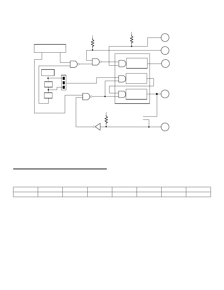
Figure 4-1 may help understand these registers, and is further explained in the section covering the 8254.
Figure 4-1. Pacer Clock and Control
4.10 ANALOG INPUT RANGE REGISTER
BASE ADDRESS +11 - Compatible Mode
G0
G1
Uni/Bip
Range
X
X
X
X
0
1
2
3
4
5
6
7
A write to this register sets the analog input range for all 8/16 analog inputs. The lower four bits set the analog input
range. The upper four bits are not used in compatible mode (Table 4-3).
13
10 MHz
2
COUNTER 0
20
COUNTER 2
COUNTER 1
A/D PACER
25
24
+5V
10K
21
+5V
10K
1 /10
1 /10
CONTROL REGISTER
BASE + 10
TRIG
CTR0
GATE
GATE
GATE
OUT
OUT
OUT
10 MHz
1MHz
+5V
10K
CIO-AD16 8254 PACER CLOCK & CONTROL
CTR 2 OUT
CTR 0 OUT
TRIGGER
GATE 0
CTR 0 IN
Advertising