Measurement Computing CIO-DAS800 User Manual
Page 12
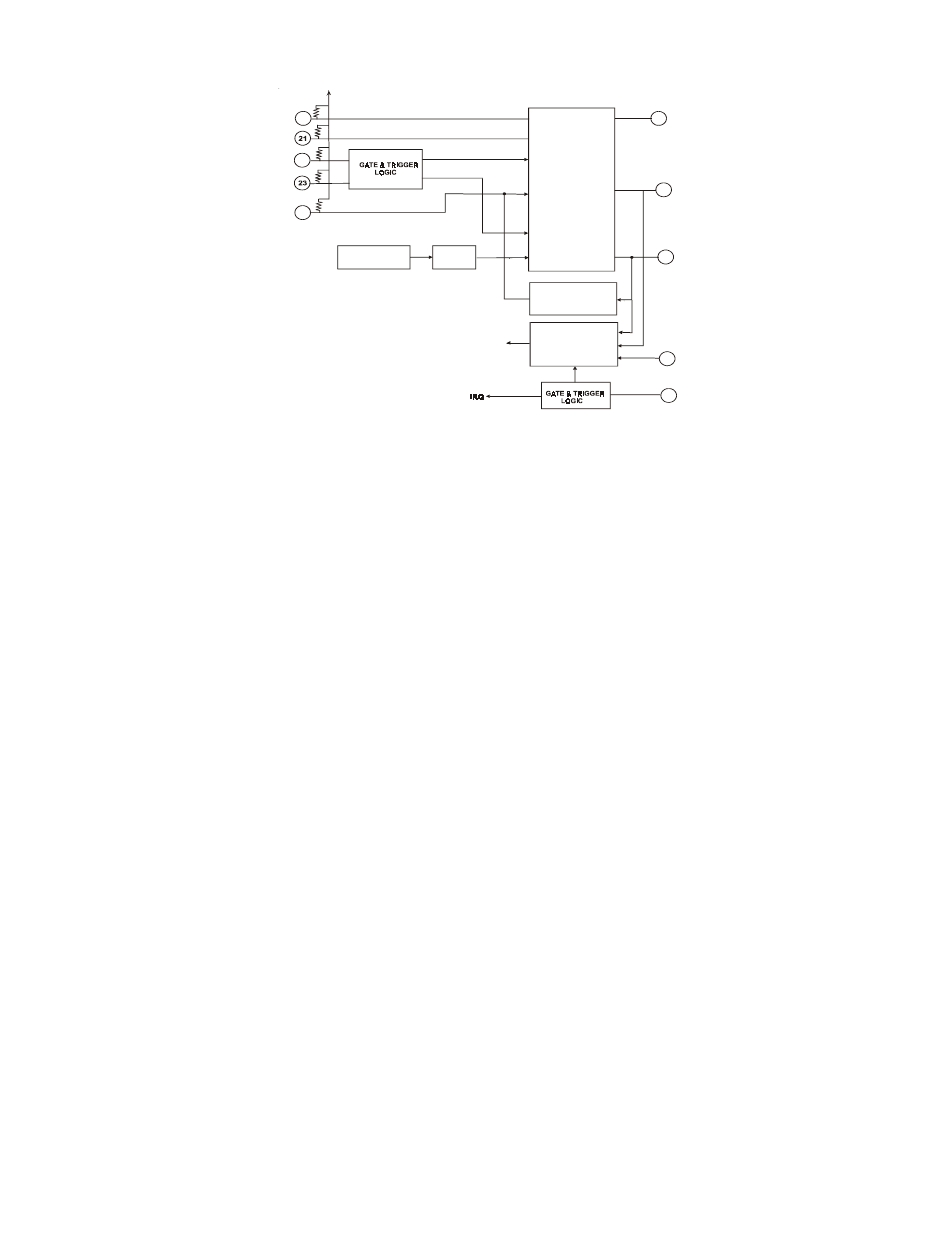
Figure 1-1. Counter/Timer Functional Diagram
Figure 1-1 shows the 82C54 functions, I/O pins and how these are connected on the CIO-DAS800.
The CIO-DAS800 CTR2 input is connected to the PC bus clock/2 or the 1 MHz. crystal signal. The
system default is the PC bus clock.
Software controls the counters that generate the A/D pacing pulse.
Note: A/D conversions are triggered by falling-edge signals. The pulses generated by the 82C54 are
low-going for one count length. The A/D is triggered as the signal goes low. Any A/D trigger signal you
supply externally must also be low-going at the desired moment of A/D conversion.
8
10 M H Z C RYS TA L
O S CILLATO R
D IV ID E B Y
10
C LK 2
C LK 1
C LK 0
C ASC A DE
C O NTR O L
LO G IC
PAC ER
C O NTR O L
LO G IC
O U T 0
O U T 1
O U T 2
C TR 0 O U T
C TR 1 O U T
C TR 2
O UT
+5V DC
+5V DC
A LL
10K
2
4
G ATE 0
G ATE 1
G ATE 2
22
INT INP UT /
XC LK
25
D IN 1/
TRIG
24
6
5
3
82C 54
STA RT CO N VE RT