Digital i/o connector and pin out, Digital i/o connections (port a0 through port c7), Digital i/o connector and pin out -3 – Measurement Computing miniLAB-1008 User Manual
Page 15
miniLAB 1008 User's Guide
Functional
Details
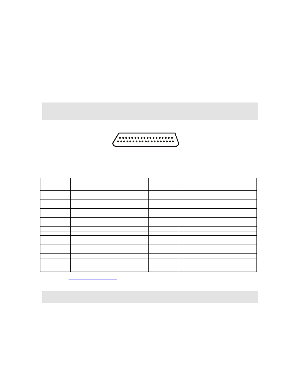
Digital I/O connector and pin out
Digital I/O connections are made to the DB37 connector on the top edge of the miniLAB 1008. This connector
provides connections for 24 digital lines (
Port A0
to
Port C7
), six ground connections (
GND
), and two power
output terminals (
USB +5V Out
and Table 3-2 for the DB37 connector pin out.
Figure 3-2. DB37 Digital I/O connector
Digital I/O connections (Port A0 through Port C7)
The 24 digital I/O pins (
Port A0-A7
,
Port B0-B7
and
Port C0-C7
) are TTL-level compatible. Each pin has a
47 kilohm (kΩ) pull-up resistor and is configured as an input by default. If needed, the miniLAB 1008 can be
factory configured to provide pull-down resistors.
Caution! Port A0 through Port C7 have no overvoltage/short circuit protection. Do not exceed the voltage
limits or you may damage the pin or the miniLAB 1008. To protect these pins, you should use a
series resistor.
19
37
1
20
Table 3-2. DB37 connector pin out
Pin Signal
Name
Pin Signal
Name
1
n/c
20
USB +5V Out
2 n/c
21 GND
3
Port B7
22
Port C7
4
Port B6
23
Port C6
5
Port B5
24
Port C5
6
Port B4
25
Port C4
7
Port B3
26
Port C3
8
Port B2
27
Port C2
9
Port B1
28
Port C1
10 Port
B0
29 Port
C0
11 GND
30 Port
A7
12 n/c
31 Port
A6
13 GND
32 Port
A5
14 n/c
33 Port
A4
15 GND
34 Port
A3
16 n/c
35 Port
A2
17 GND
36 Port
A1
18
USB +5V Out
37
Port A0
19
GND
Refer to the "
" section for descriptions of cables that are compatible with the DB37
digital I/O connector.
Caution! The
USB +5V Out
pins on the DB37 connector are outputs. Do not connect an external 5 V supply
or you may damage the miniLAB 1008 and possibly the computer.
3-3