Measurement Computing PCI-DIO24/S User Manual
Page 14
PCI-DIO24/S User's Guide
Functional Details
14
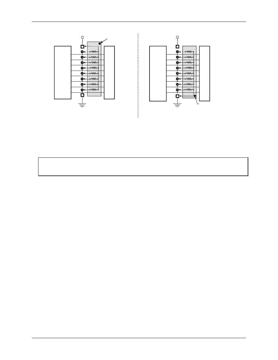
2.2 K SIP installed for pull-up
2.2 K SIP
Dot indicates the
common line
+5 VDC
HI
LO
(GND)
n7
U
s
e
r
C
o
n
n
e
c
to
r
D
ig
it
a
l
I/
O
L
in
e
s
n5
n4
n3
n2
n1
n0
n6
COM
Digital
I/O Port
n = A, B, or C
+5 VDC
2.2 K SIP installed for pull-down
2.2 K SIP
Dot indicates the
common line
HI
LO
(GND)
n7
U
s
e
r
C
o
n
n
e
c
to
r
D
ig
it
a
l
I/
O
L
in
e
s
n5
n4
n3
n2
n1
n0
n6
COM
Digital
I/O Port
n = A, B, or C
Figure 7. Pull-up and pull-down resistor SIP schematic
To pull up the digital lines for a particular port, install the resistor with the common pin at the
HI
end. To pull
down the digital lines for a particular port, install the resistor with the common pin at the
LO
end. When
installed, the SIP resistors establish either a high or low logic level for each port when the board is in input
mode.
Install MCC SIP packs
When installing pull-up and pull-down resistor SIP packs, we recommend using a 2.2 K, eight-resistor SIP
(MCC part number SP-K2.29C).