Cabling – Measurement Computing PCIe-DIO96H User Manual
Page 11
PCIe-DIO96H User's Guide
Installing the PCIe-DIO96H
11
Cabling
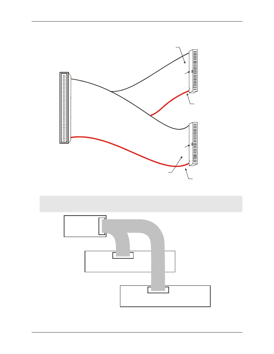
Figure 2. C100FF-x cable
Caution! When connecting the cable to the board's I/O connector, make sure that the arrow indicating pin 1
on the board connector lines up with the arrow indicating pin 1 on the cable connector. Incorrectly
connected cables can damage the board and the I/O controller.
Figure 3. C100FF-x cable configuration
1
50
2
49
51
100
52
99
100
50
51
1
Key
Key
The red stripe
identifies pin # 1
The red stripe
identifies pin # 51
Cable is labeled
“Pins 51-100”.
Cable is labeled
“Pins 1-50”.
IN
100-pin
I/O connector
Digital I/O
pins 1 to 50
Digital signal conditioning or
50-pin screw terminl board
Digital I/O
pins 51 to 100
C100FF-x cable
IN
Digital signal conditioning or
50-pin screw terminl board