Functional description, Isolated inputs, Extending the input range – Measurement Computing PCI-PDISO16 User Manual
Page 16
16
Chapter 3
Functional Description
Isolated inputs
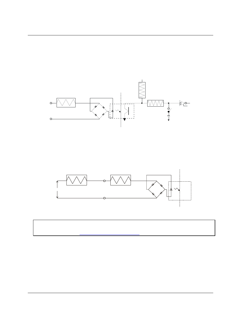
The PCI-PDISO16 board has eight isolated input channels. A schematic of a single channel is shown in Figure
6. The signals are routed through a bridge rectifier so that the inputs are not polarity sensitive.
470 Ohm
Isolated Input
Not Polarized
Circuitry Sharing
PC Ground
Filter Switch
0.1uF
47K
+5V
100K
Figure 6. Isolated input channel - simplified schematic
Extending the input range
To extend the input range beyond the 5-28V specified, add an external resistor. Figure 7 shows the resistor and
the equations used to calculate resistor values for a given V
in
.
1.6 K
Isolated Input
Not Polarized
R ext
V
in
R ext = 100 * (Vin - 28)
Pw = R ext / 10 000
Figure 7. Input voltage range extender resistor
Digital I/O Techniques
For more information about digital I/O techniques, refer to the Guide to Signal Connections. This document is
available on our web sit