Installing the software, Configuring the pci-quad04, Channel input mode – Measurement Computing PCI-QUAD04 User Manual
Page 9: Termination resistors
PCI-QUAD04 User's Guide
Installing the PCI-QUAD04
9
Installing the software
Refer to the Quick Start Guide for instructions on installing the software on the Measurement Computing Data
Acquisition Software CD. This booklet is available in PDF at
www.mccdaq.com/PDFmanuals/DAQ-Software-
Quick-Start.pdf
.
Configuring the PCI-QUAD04
Before installing the board, configure the channel input mode for either single-ended or differential. You set the
channel configuration with a set of jumper blocks on the board. Each jumper is labeled for its functionality. By
default, the board is shipped with the channels configured for single-ended operation, with no termination
resistors installed.
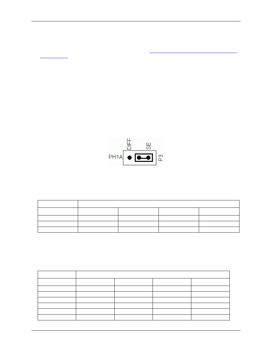
Channel input mode
To configure for single-ended operation, place a jumper between pin 2 and pin 3 (labeled
SE
). To configure for
differential operation, place a jumper between pin 1 (labeled
DIFF
) and pin 2. A single-ended configuration is
shown in Figure 3.
Figure 3. Channel input mode configured for SE operation
Input mode jumper settings are listed in the table below.
Channel input mode jumper settings
Input channel
Input
1
2
3
4
Phase A
P3
P8
P14
P11
Phase B
P4
P7
P13
P10
Index
P5
P6
P12
P9
Termination resistors
Although termination resistors typically are not required, SMT pads on the PCI-QUAD04 are open and labeled
to allow you to install terminating resistors from the various inputs to ground.
Termination resistor settings
Channel
Input
1
2
3
4
Phase A+
R9
R22
R38
R30
Phase A-
R10
R23
R39
R31
Phase B+
R11
R20
R36
R28
Phase B-
R12
R21
R37
R29
Index+
R14
R19
R35
R27
Index-
R13
R18
R34
R26