Extending the input range – Measurement Computing SWITCH AND SENSE 8/8 User Manual
Page 16
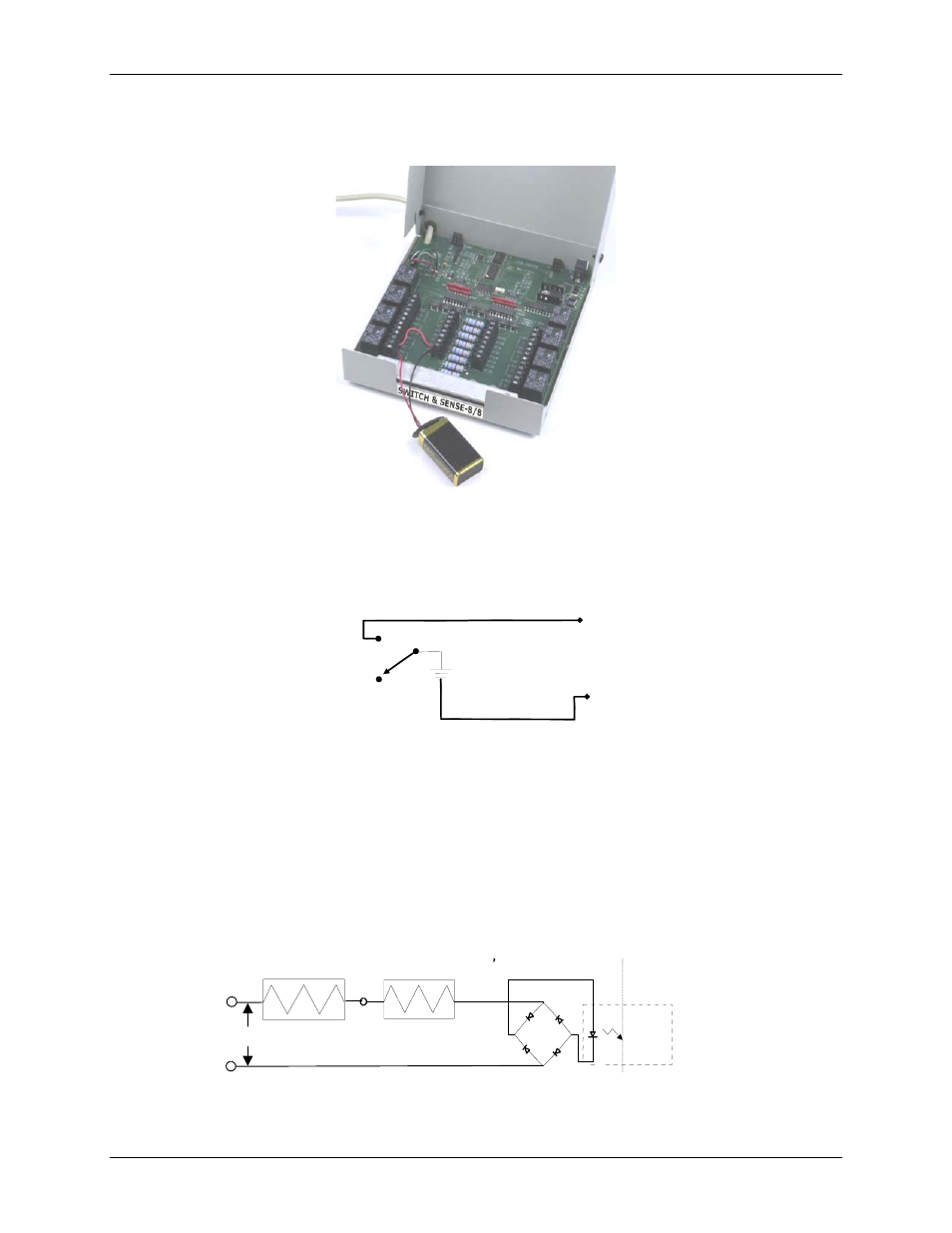
Switch & Sense 8/8 User's Guide Functional
Details
3-5
Figure 3-6 illustrates a simple connection from a +9 V battery to the relay 4 terminals. When the relay is
energized, the relay 4 NO terminal connects the battery voltage to the input 4 terminal (IP4B).
Figure 3-6. Simple battery-to relay connection
Figure 3-7 shows the schematic of this connection.
IP4A
IP4B
NC
NO
C
+9 V
Figure 3-7. Schematic of battery-to relay connection
Extending the input range
You can extend the input range beyond the 5 to 30 V specified by adding an external resistor. Figure 3-8 shows
the external resistor (R
ext
).
The equation R
ext
= 100 * (V
in
– 30) calculates the resistor value for a given V
in
.
Make sure the external resistor is capable of handling the power generated by the input. Calculate the power
requirement in watts (P
w
) using the equation P
w
= R
ext
/10000.
1.6 K
V
in
R
ext
= 100 * (V
in
– 30)
P
w
= R
ext
/10000
R
ext
Figure 3-8. External resistor added to extend input range