Digital i/o, Pull-up/down configuration – Measurement Computing USB-1208HS-4AO User Manual
Page 13
USB-1208HS-4AO User's Guide
Functional Details
13
You can connect an external clock signal to
AICKI
and/or
AOCKI
.
When using an external clock,
AICKO
outputs the pulse generated from
AOCKI
, and
AOCKO
outputs the
pulse generated from
AOCKI
When using the internal clock,
AICKO
outputs the
ADC scan clock, and
AOCKO
outputs the
DAC scan
clock.
Digital I/O
You can connect up to 16 digital I/O lines to screw terminals
DIO0
through
DIO15
. The terminals have 47 k
Ω
resistors that you can configure for pull-up or down using an internal jumper. The default configuration is
pull-down.
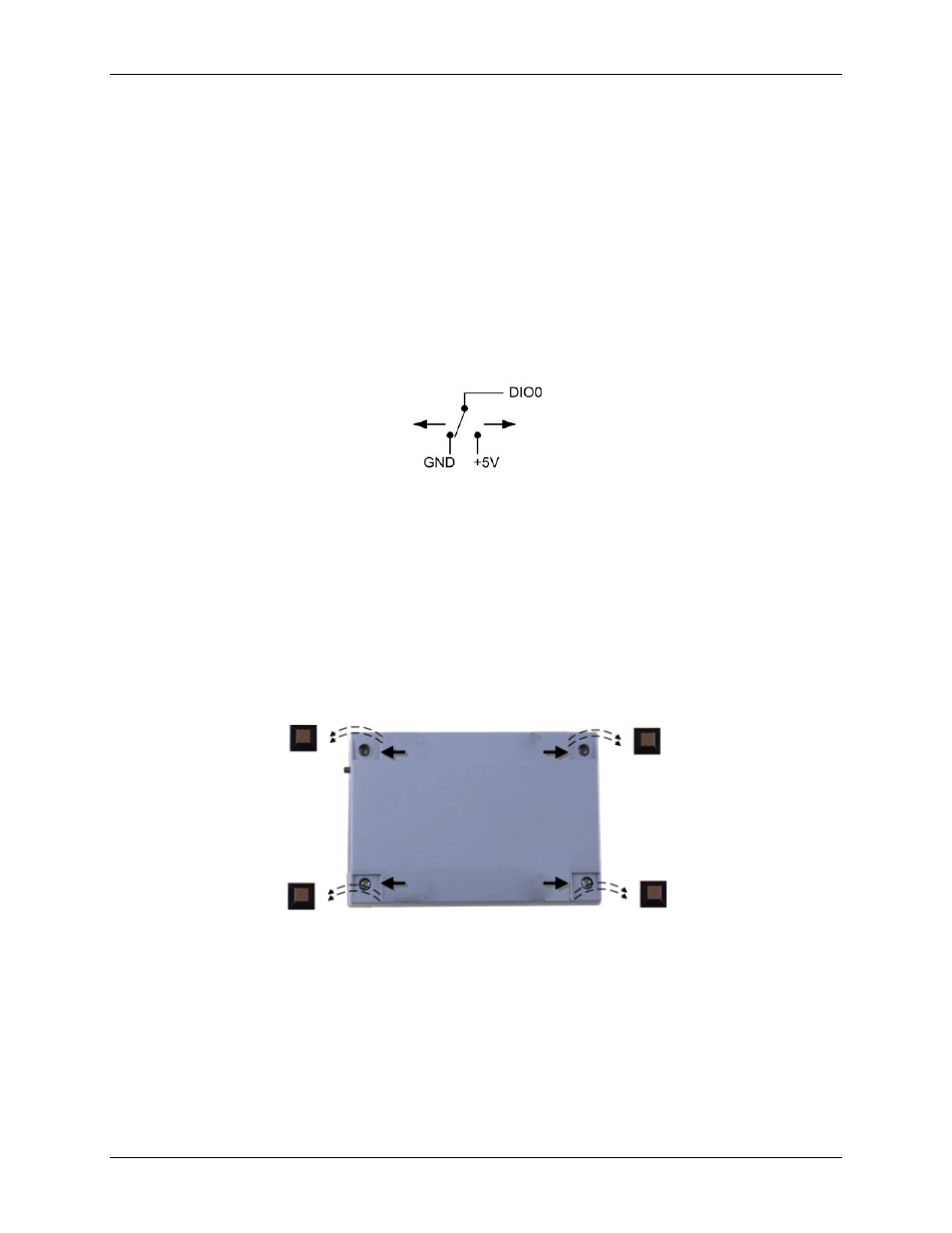
You can use the digital I/O terminals to detect the state of any TTL-level input. Refer to the schematic in Figure
7. If you set the switch to the +5 V input, DIO0 reads TRUE (1). If you move the switch to GND, DIO0 reads
FALSE (0).
Figure 7. Schematic showing switch detection by digital channel DIO0
Pull-up/down configuration
Each of the 16 DIO bits on the USB-1208HS-4AO has a 47
kΩ pull-up/pull-down resistor. To configure these
bits for either a +5 V pull-up or a 0 V pull-down option, you must open the USB-1208HS-4AO case to access
the three-pin jumper labeled W34.
The pull-up/pull-down voltage is common to all of the internal 47
kΩ resistors.
To open the case and set the W34 jumper, do the following.
1. Turn over the USB-1208HS-4AO and rest it on its top on a flat, stable surface.
2. Peel off the four rubber feet on the bottom of the module to access the screws.
3. Remove the four screws shown in Figure 8 from the bottom of the device.
Figure 8. Location of screws connecting bottom and top sections of case
4. Holding both the top and bottom sections of the module, turn it back over, rest it on the surface, and
carefully remove the top section of the case.
5. Set the jumper to either pull-up or pull-down (see Figure 9 and Figure 10).