External components, Usb connector, Screw terminals – Measurement Computing USB-1608FS-Plus User Manual
Page 10
USB-1608FS-Plus User's Guide
Functional Details
10
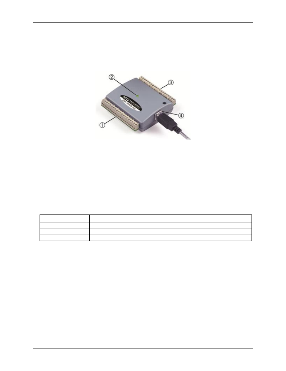
External components
The external components – screw terminal banks, LED, and USB connector –are shown in Figure 2.
Screw terminals
LED
USB connector
1
Screw terminal pins 21 to 40
3
Screw terminal pins 1 to 20
2
LED
4
USB connector
Figure 2. USB-1608FS-Plus components
USB connector
Receives the supplied USB cable. When connected to a computer or USB hub, the cable provides +5 V power
and communication. No external power supply is required.
LED
The LED indicates the communication status; it cannot be disabled.
LED behavior
LED state
Indication
On – steady green
The device is connected to a computer or external USB hub.
Blinks once
A USB command is received.
Blinks continuously
An analog input scan is in progress.
Screw terminals
The screw terminals provide the following connections:
Eight analog inputs (
CH0 IN
to
CH7 IN
)
Eight digital I/O lines(
DIO0
to
DIO7
)
One external event counter input (
CTR
)
One SYNC I/O terminal for external clocking and multi-unit synchronization (
SYNC
)
One external trigger input (
TRIG_IN
)
One power output (
PC+5 V
)
11 analog ground (
AGND
) and eight digital ground (
GND
) connections
Use 16 AWG to 30 AWG wire when making connections to the screw terminals. Pinout locations are shown in
Figure 3.