External components, Usb connector, Screw terminals – Measurement Computing USB-1608FS User Manual
Page 10
USB-1608FS User's Guide
10
External components
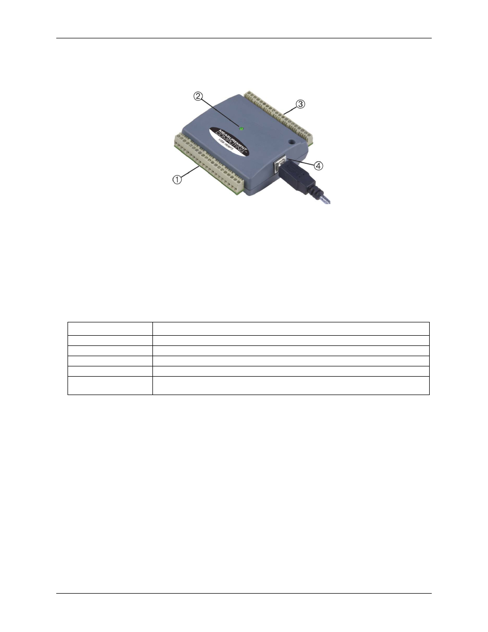
The external components – screw terminal banks, LED, and USB connector –are shown in Figure 2.
1 Screw terminal pins 21 to 40 3 Screw terminal pins 1 to 20
2 LED
4 USB connector
Figure 2. USB-1608FS components
USB connector
The USB connector provides +5 V power and communication. No external power supply is required.
LED
The LED indicates the communication status; it cannot be disabled. LED states are listed in the table below.
LED behavior
LED state
Indication
On – steady green
The device is connected to a computer or external USB hub.
Blinks once
A USB command is received.
Blinks continuously
Data is being transferred.
Blinks three times
Initial communication is established between the USB-1608FS and the computer.
Blinks at a slow rate
The analog input is configured for external trigger. The LED stops blinking and illuminates
steady green when the trigger is received.
Screw terminals
The screw terminals provide the following connections:
Eight analog inputs (
CH0 IN
to
CH7 IN
)
Eight digital I/O lines(
DIO0
to
DIO7
)
One external event counter input (
CTR
)
One SYNC I/O terminal for external clocking and multi-unit synchronization (
SYNC
)
One external trigger input (
TRIG_IN
)
One calibration output (
CAL
)
One power output (
PC +5 V
)
analog ground (
AGND
) and digital ground (
GND
) connections