External clock i/o, Digital i/o, Pull-up/down configuration – Measurement Computing USB-1608GX-2AO-OEM User Manual
Page 14
USB-1608GX-2AO-OEM User's Guide
Functional Details
14
External clock I/O
The USB-1608GX-2AO-OEM provides one external clock input (
AICKI
) and one external clock output
(
AICKO
) for analog inputs, and one external clock input (
AOCKI
) and one external clock output (
AOCKO
) for
analog outputs.
You can connect an external clock signal to
AICKI
and/or
AOCKI
.
When using an external clock,
AICKO
outputs the pulse generated from
AICKI
, and
AOCKO
outputs the
pulse generated from
AOCKI
.
When using the internal clock,
AICKO
outputs the
ADC scan clock, and
AOCKO
outputs the
DAC scan
clock.
Digital I/O
You can connect up to eight digital I/O lines to
DIO0
through
DIO7
. Each digital channel is individually
configurable for input or output. The digital I/O terminals can detect the state of any TTL-level input. Refer to
the schematic shown in Figure 5.
Figure 5. Schematic showing switch detection by digital channel DIO0
If you set the switch to the +5 V input, DIO0 reads TRUE (1). If you move the switch to GND, DIO0 reads
FALSE (0).
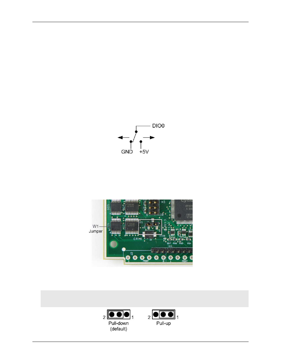
Pull-up/down configuration
Unconnected inputs are pulled low by default to 0 V through 47
kΩ resistors via jumper
W1
on the circuit board
Figure 6. W1 jumper location
The pull-up/pull-down voltage is common to all 47
kΩ resistors. Jumper W1 is configured by default for pull-
down. Figure 7 shows the jumper configured for pull-up and pull-down.
Caution! The discharge of static electricity can damage some electronic components. Before touching the
board, ground yourself using a wrist strap or touch the computer chassis or other grounded object
to eliminate any stored static charge.
Figure 7. W1 jumper configurations