Synchronized operations, N figure 9 – Measurement Computing USB-7202 User Manual
Page 17
USB-7202 User's Guide
Functional Details
17
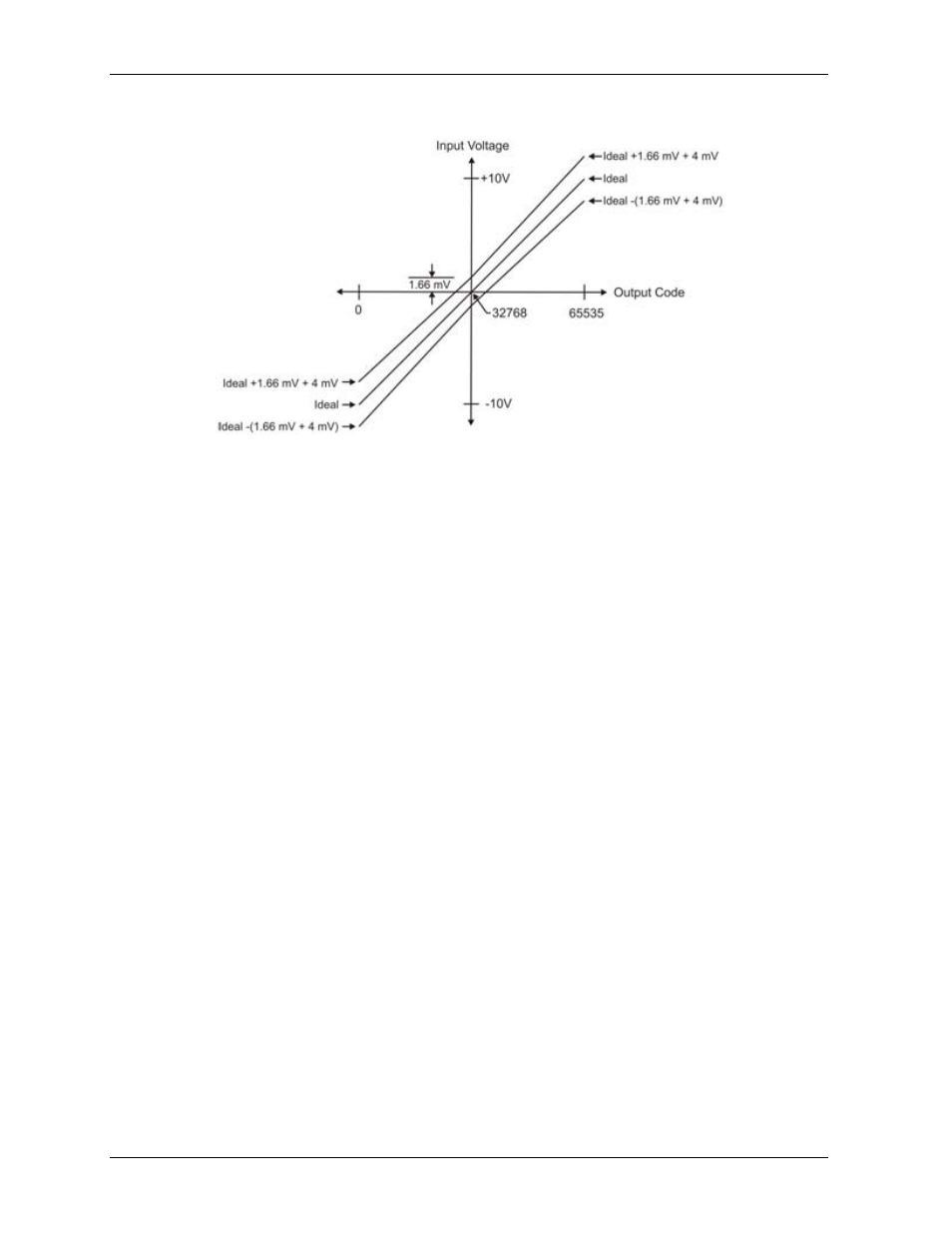
The accuracy plots in Figure 9 are drawn for clarity and are not drawn to scale.
Figure 9. Error band plot
Synchronized operations
You can connect the SYNC pin of two USB-7202 devices together in a master/slave configuration and
acquire data from the analog inputs of both devices using one clock. When the SYNC pin is configured as an
output, the internal A/D pacer clock signal is sent to the screw terminal. If jumper P6 is installed, you can
output the clock to the SYNC pin of a second USB-7202 configured for A/D pacer input.
The SYNC pin is available on both the screw terminal connector and on the Trigger/SYNC connector (when
jumper P6 is installed). Refer to page 14 for more information about the SYNC pin.