Analog input calibration, Throughput rate, Digital i/o – Measurement Computing USB-TC-AI User Manual
Page 19
USB-TC-AI User's Guide
Specifications
19
Analog input calibration
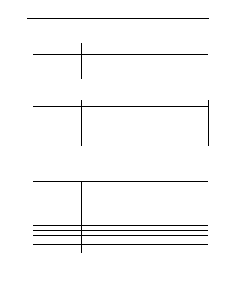
Table 9. Analog input calibration specifications
Parameter
Specification
Recommended warm-up time
30 minutes min
Calibration
Firmware calibration
Calibration interval
1 year
Calibration reference
+10.000 V, ±5 mV max. Actual measured values stored in EEPROM
Tempco: 5 ppm/°C max
Long term stability: 30 ppm/1000 h
Throughput rate
Table 10. Throughput rate specifications
Number of Input Channels
Maximum throughput
1
2 S/s
2
2 S/s on each channel, 4 S/s total
3
2 S/s on each channel, 6 S/s total
4
2 S/s on each channel, 8 S/s total
5
2 S/s on each channel, 10 S/s total
6
2 S/s on each channel, 12 S/s total
7
2 S/s on each channel, 14 S/s total
8
2 S/s on each channel, 16 S/s total
Note 11:
The analog inputs are configured to run continuously. Each channel is sampled twice per second.
The maximum latency between when a sample is acquired and the voltage/temperature data is
provided by the USB unit is approximately 0.4 seconds.
Digital I/O
Table 11. Digital input/output specifications
Parameter
Specification
Digital type
5V CMOS
Number of I/O
8 (DIO0 through DIO7)
Configuration
Independently configured for input or output.
Power on reset is input mode.
Pull-up/pull-down
configuration
All pins pulled up to +5 V via 47 K resistors (default). Contact MCC factory for pull-
down to ground (GND) capability.
Digital I/O transfer rate
(software paced)
Digital input: 50 port reads or single bit reads per second typ
Digital output: 100 port writes or single bit writes per second typ
Input high voltage
2.0 V min, 5.5 V absolute max.
Input low voltage
0.8 V max, –0.5 V absolute min
Output low voltage
(IOL = 2.5 mA max)
0.7 V max
Output high voltage
(IOH = -2.5 mA max)
3.8 V min
Note 12:
All ground pins on the USB-TC-AI (pins 9, 19, 22, 27, 30, 33, 36, 39, 49) are common and are
isolated from earth ground. If a connection is made to earth ground when using digital I/O and
conductive thermocouples, the thermocouples are no longer isolated. In this case, thermocouples must
not be connected to any conductive surfaces that may be referenced to earth ground.