Measurement Computing WBK10A User Manual
Page 2
pg. 2, WBK10A
988397
WBK10A, Analog Expansion Module
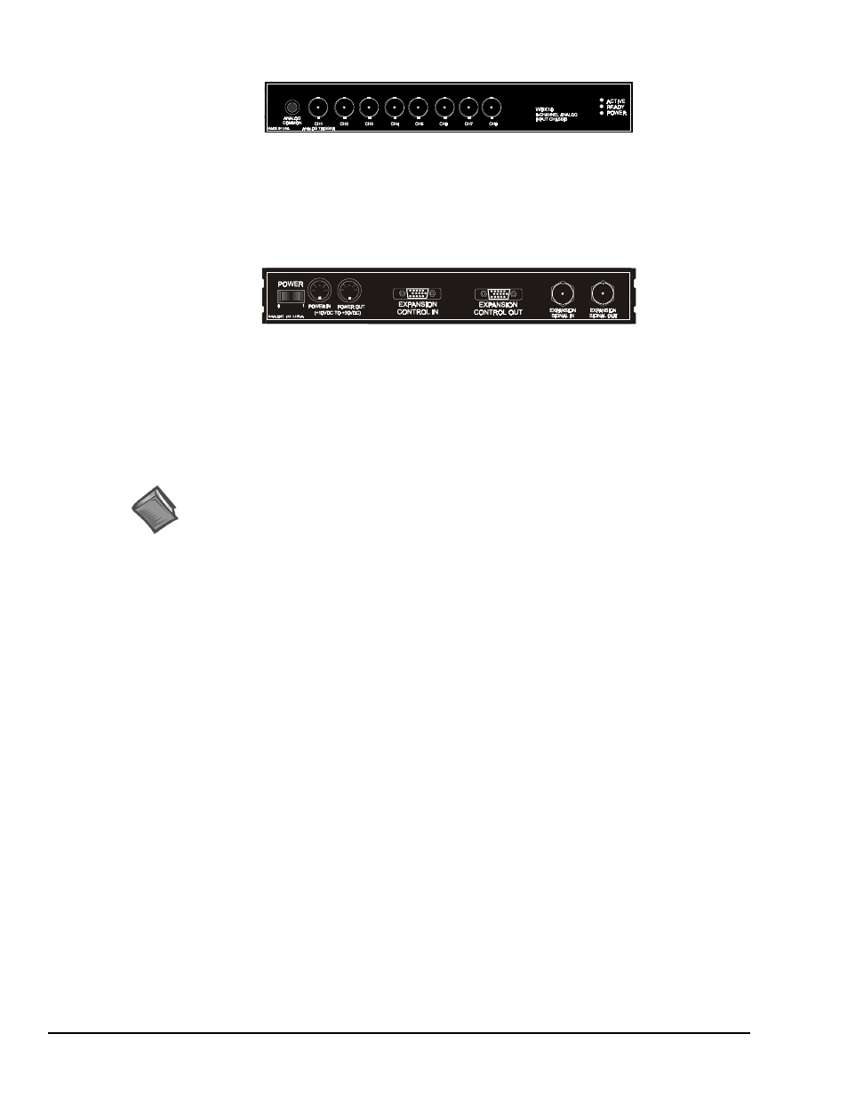
The front panel has the following connectors and indicators:
WBK10A Front Panel
• 1 Analog Common binding post for reference.
• 8 BNC connectors for analog inputs. Channels are labeled 1 through 8.
• 3 Status LEDs (Active, Ready, Power).
The rear panel has a power switch and the following connectors:
WBK10A Rear Panel
• 2 DIN5 connectors [one for Power In, one for Power Out]
• 1 HD-15M Expansion Control In
• 1 HD-15F Expansion Control Out
• 2 BNC connectors [one for analog Expansion Signal In,
one for analog Expansion Signal Out]
Reference Notes:
➣
Setup information pertaining to power, expansion control, and expansion signal connections
is contained in the
System Setup and Power Options
chapter of the WaveBook User’s
Manual (p/n 489-0901).
➣
For detailed WaveView information, refer to the
WaveView Document Module
that is
included on the data acquisition CD. The document can be accessed using the
<View PDFs> button on the CD’s opening screen.