Processing, A detailed description, Input conditioning – Metric Halo Production Bundle User Manual
Page 75: Crossover, 75 input conditioning, 75 crossover, Multiband dynamics signal flow, 75 15.2. crossover controls, Three-way crossover
75
15. Processing
A Detailed Description
In this chapter we'll discuss what each processing block does and how the controls work.
High
Compressor
Output
Gain
Input
Output
SpectraFoo
Limiter
Crossover
Mid
Compressor
Low
Compressor
Input Gain
Band Solos
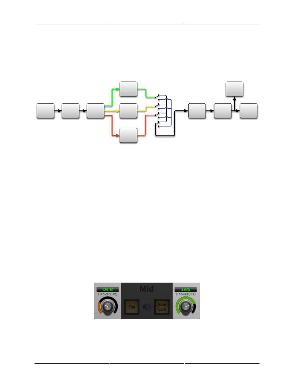
Figure 15.1: Multiband Dynamics Signal Flow
The block diagram above illustrates the overall structure of the processing system provided by Multiband
Dynamics. The diagram does not indicate the various metering blocks.
Now lets examine the various processing blocks indicated in the diagram.
Input Conditioning
After the signal is routed to Multiband Dynamics it runs through an input gain block that provides input gain
of up to +30 dB. You can use this gain to condition signals that are low in level.
This input gain may also be used to pad out signals by up to –30 dB. While you may find this attenuation useful
to just bring down the level through the strip simply and quickly, you must realize that this gain is applied after
the signal reaches Multiband Dynamics and will not pad out any clipping that occurs in the A/D converters
or in a plug-in that is inserted before Multiband Dynamics.
The input gain is controlled by the “In Gain” knob.
Crossover
The crossover seperates the audio input into low, mid and high bands; each of these bands is then fed through
a compressor section. There are two controls to set the crossover points:
Figure 15.2: Crossover Controls
The control marked “LXover” sets the frequency of the low to mid crossover, and the control marked “HXover”
sets the frequency of the mid to high crossover.