Power strip / cord wrap – Metro Power Strip / Cord Wrap Mounted on Overbridge User Manual
Page 2
PART # SX595
Assembly consists of (1) Hospital Grade, 6 outlet, 15-ft Power Strip, (1) Cord Wrap,
(2) Hardware Bag
1.
On the rear of the power strip place (2) #6-32 x 3/8 screws into the keyhole slots, trapping the heads in the
slots.
2.
Place power strip against the long plate on the cord wrap inserting the screws through the mounting holes.
Secure with (2) #6-32 nuts.
3.
In the holes on the cord wrap short plates, insert (2) #8-32x ¼ screws and start (2) cam nuts onto screws. The
raised circle on the cam nuts must face toward the screw. Leave loose.
4.
The power strip/ cord wrap assembly can be mounted on either rear corner of the Starsys unit, however, one
corner will have the post filler strip removed at the factory for mounting. Determine the mounting height
location on the post and mark the cut locations on the filler strip. Two (2) 1” long sections must be cut out of
the filler strip in order for the cam nuts to be inserted into the post slot per the illustration below. Use a sharp
utility knife to score the sections, then snap them in half.
5.
Insert cam nuts into the post slots and tighten. Make sure cam nuts lock into the post slot.
6.
Insert the post filler strip sections into the post slot by pressing firmly and snapping them into place.
7.
Loop cord around wrap.
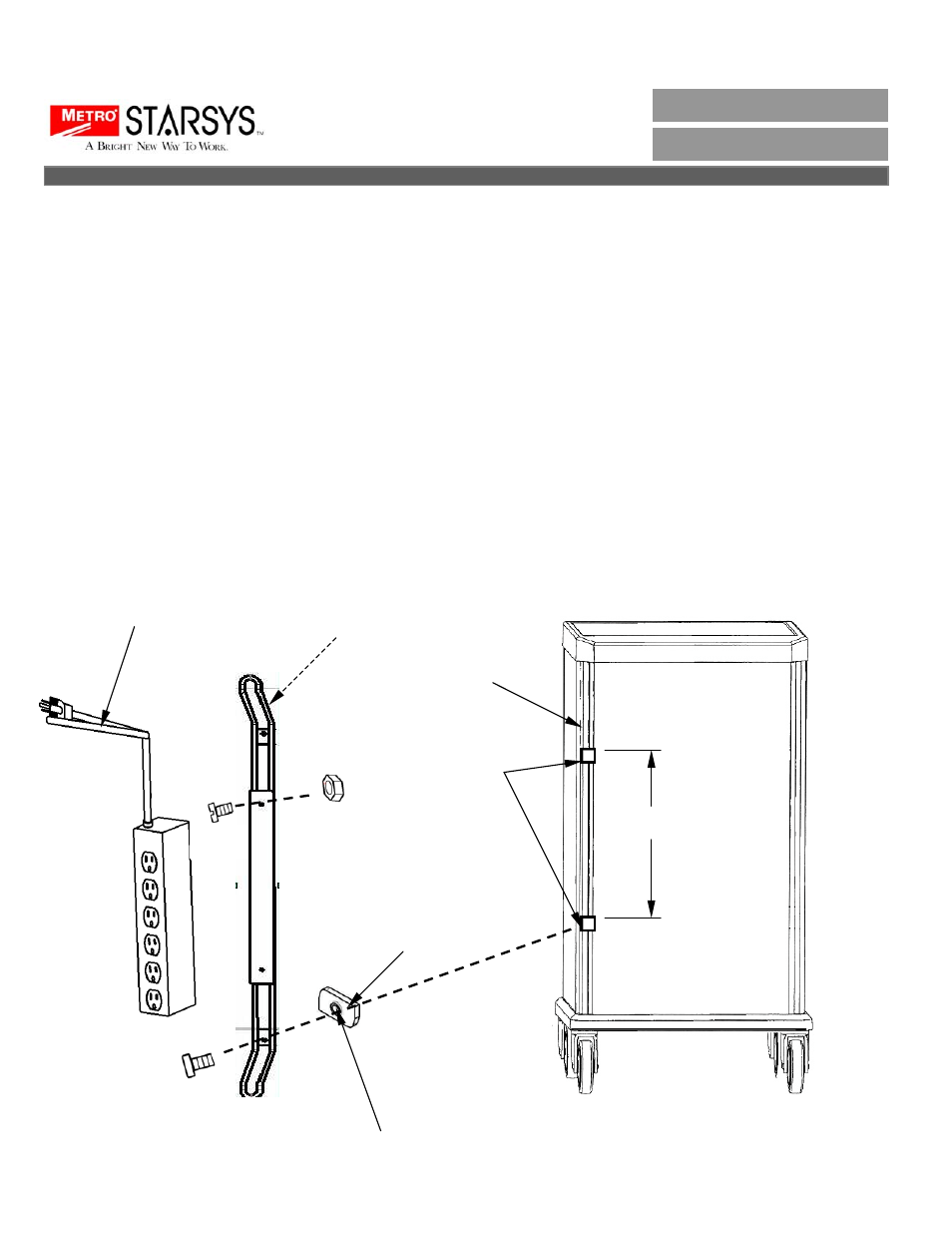
Power Strip / Cord Wrap
INSTALLATION
INSTRUCTIONS
X 2
Cord Wrap
Cam Nut
Raise circle on nut to
face towards screw
X 2
X 2
X 2
Power Strip
Plastic Post
Filler Strip
Cut outs for
cam nuts
Rear of Starsys
21”
INST-SX595
Rev. 4/04