Installation, Optional doors, Upgrading to the -s2 heating insert – Montigo SP28 F2 User Manual
Page 8
XG0318
Page 8
SP28-F2 Modular Series Fireplace
Installation
Optional Doors
EP28 Series Decorative Models come standard with a firescreen, and
may be fitted with one of the following optional door kits:
n
Twin-Pane-Style Doors ................ Part # ETW28
n
Bi-Fold Doors
....................... Part # EBD28
n
Stereo Cabinet Doors ................... Part # ETWD28E
Twin-Pane and Bi-Fold Doors are available in Black, Brass or Nickel
Finshes to match your fireplace's trim. Stereo Cabinet Doors are an all-
glass design.
The EP28-S2 Heating Insert includes a fixed glass door, and cannot be
fitted with the above doors.
Installation
Complete installation instructions are included with the door kit.
Adjustment
After installation of the fireplace, the doors may require some adjustment.
The spring clips that are installed on both sides of the top door rail are
used to align the doors. With the door open, loosen the screw that holds
the spring clip in place (see Inset). This will allow the door to move back
and forth. Fit the doors so that they are straight and tighten the screw to
hold the door in position. Adjust both doors until the opening between the
doors, when closed, is even from top to bottom.
Figure 12.
Adjusting the glass doors.
Spring Clip
Top Door Rail
Bottom Door Rail
Inset
Pivot Point
Upgrading to the
-S2 Heating Insert
1. Remove the upper and lower trims.
Warning: You must turn off gas supply to the fireplace.
2. Remove the doors and mesh firescreen, if installed.
3. Remove the bottom door rail, as shown if Figure 13.
Figure 13.
Removing the bottom door rail.
4. Disconnect the gas supply line from the control valve under the
fireplace. Remove the two screws located at bottom rear of burner
pan. Disconnect the primary spill switch from the gas valve. Leave
the primary spill switch in it's location, as it must be re-wired to
complete the new burner assembly installation. Lift the complete
burner assembly, up and out of unit to clear support ledge. See
figure 14. Remove the existing fan assembly, if installed.
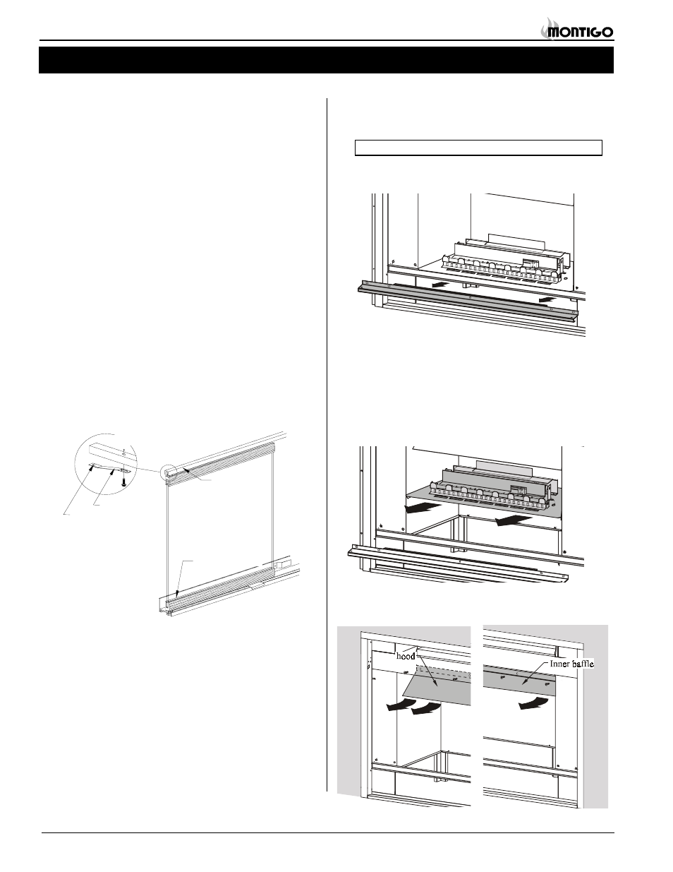
5. Remove the hood and inner baffle, as shown in figure 15.
Figure 14.
Removing the old burner assembly.
Figure 15.
Removing the decorative burner hood and inner baffles.