3 connections, 1 connecting to the dwdm-40c, 2 system design – Nevion DWDM-40C User Manual
Page 7
DWDM-40C
Rev. A
nevion.com | 7
3 Connections
3.1 Connecting to the DWDM-40C
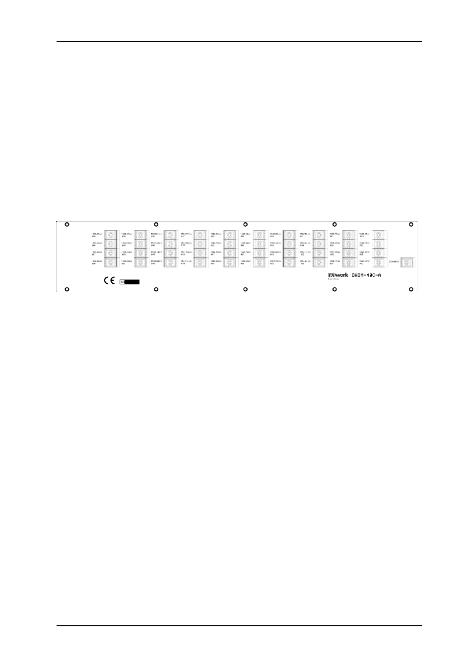
Figure 2.11 shows the backplane for the flashlink 40-channel DWDM optical filter frame.
Each optical port supports a dedicated wavelength that is marked on the sub-rack frame. The
connector is an SC/PC connector. Each port should be connected to the corresponding
wavelength for each channel card with an optical patch cord. The common port supports all
wavelengths in either direction and should therefore be connected to the single fiber between
the two locations where the flashlink 40-channel DWDM system is installed. The optical
filters are sold in pairs using cascaded thin film filters for wavelength selection. This means
that the filters are mounted in opposite orders on the two sides. Those wavelengths which
have lower attenuation in one end point have higher attenuation in the other end point, thus
ensuring all channels have the same link loss. The specification of the optical filters can be
found in chapter 2. One side is marked DWDM-40C-A, the other is marked DWDM-40C-B.
Figure 3.1: The backplane for the 40-channel DWDM system optical filter (endpoint A)
3.2 System design
The maximum insertion loss for any channel in end point A is 4.0dB, but the same channel in
the complementary end point B will then have a maximum insertion loss of 1.5dB. Likewise
the channel with maximum allowed insertion loss of 1.5dB in endpoint A will have a
maximum insertion loss of 4.0dB in end point B. This means that there can theoretically be
about 3dB difference in attenuation between two different channels (1.5dB variance across
the band) after multiplexing. When using erbium doped fiber optical amplifiers (EDFA), this
can lead to large differences in signal strength between different channels at the receiving
end. The reason is that EDFAs also have a variance in gain across the wavelength band.
Therefore a special uniform loss version (suffix -U) is available as an option.
EDFAs used with DWDM-40C should have a gain flattening filter and operate close to
nominal gain / input power. When operating over or under nominal gain, the EDFAs gain
variance changes drastically.
The minimum headroom that needs to be considered when designing a system increases for
each EDFA because of the gain variance across wavelengths.