3 9-40 channel system – Nevion DWDM-8C User Manual
Page 8
DWDM-8C
Rev. B
nevion.com | 8
Figure 4: 8 channel filter connected to main fibre
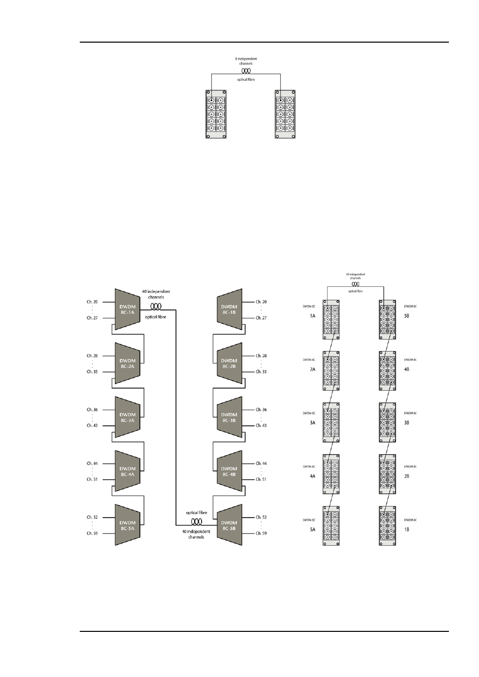
3.3 9-40 channel system
Each set of 8 channels must first be connected like described in Chapter 3.2, Figure 3.
Next, the frames are interconnected, endpoint “A” should be opposite of endpoint “B”
for optimum performance. For endpoint “A”, the common port of module 1A would
typically be the common port of the whole system, connected to the outside world. The
upgrade port of module 1 would connect to the common port of module 2A, and so on.
For endpoint “B”, the common port of module 5B would connect to the outside world
(and thus to common port of 1A), while the upgrade port of 5B would connect to the
common port of 4B.
Figure 5: Optimal interconnection of a 40 channel system
This way, the insertion loss can be considered to be identical for all channels in a 40
channel system. If the system is set up in a different way, some channels will see less
insertion loss, while others see more. This limits the optical budget. If the optical budget