3 detailed control, 1 detailed control in manual mode, 1 rotary switch and push buttons – Nevion SPG-AVA-DMUX User Manual
Page 10: 2 dip switch functions, 3detailed control
SPG-AVA-DMUX
Rev. C
nevion.com | 10
3
Detailed control
3.1 Detailed control in manual mode
To reach manual mode, the lower DIP (labelled OVR) on the module must be switched to the
“On” position (to the right) and the board must be re-booted. This isolates the board from
Multicon GYDA control, but the module will still accept commands to retrieve its status, and
also commands related to initiate and perform firmware upgrades.
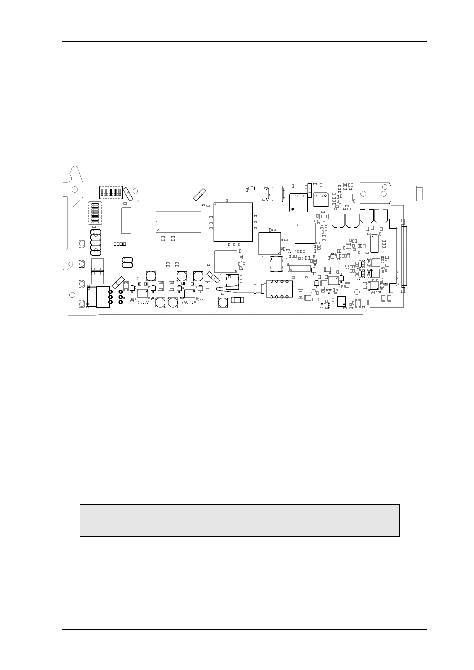
The Manual Mode configuration controls are all found on the front side of the board. There
are two sets of DIP switches, one rotary switch, and two push buttons.
Figure 3: The figure shows a top view component printout of the board
3.1.1 Rotary switch and push buttons
The rotary switch and the push buttons are used to control the phase delay setting of the
frame-synchronizer. They are accessible from the front of the module and are meant to be
adjusted when the module is powered and active. No change will be seen in output video
unless a sync input (black & burst or tri-level) is present.
The rotary switch, labelled DLY, adjusts the phase delay from -5 to +4 video lines.
The push buttons, labelled INC and DEC, are used to fine adjust the phase delay one sample
at a time. They can adjust the additional samples setting within +/- ½ video lines for the
present video standard. Pressing both buttons simultaneously will reset the number of
additional samples to 0. Holding one of the buttons in will accelerate the increase/decrease
action until the button is released (or one of the limits -½ or +½ video lines is reached). When
the samples setting is reset or one of the limits reached, this will be acknowledged with a
series of short flashes on the LED(s) closest to the activated button(s).
3.1.2 DIP switch functions
The two horizontally mounted DIP switch packages are here denoted DIP1-
DIP16, counted from left to right. The vertically mounted DIP package is denoted
with DIP17-DIP24, counted from top to bottom.